Joint prosthesis with infinitely positionable head

a joint prosthesis and infinite position technology, applied in the field of joint prosthesis, can solve the problems of humeral prosthesis often only achieving the best-fit relationship, more wear and tear on the joint, and increased risk of serious joint injuries

Active Publication Date: 2005-06-30
DEPUY SYNTHES PROD INC
View PDF54 Cites 84 Cited by
  • Summary
  • Abstract
  • Description
  • Claims
  • Application Information

AI Technical Summary

Benefits of technology

[0007] These and other needs of the prior art are met by the present invention in which a joint component is itself mounted to a bone engaging component of a prosthesis by an articulating

Problems solved by technology

Longer life spans mean that the joints endure more wear and tear.
More sports activities mean greater likelihood of serious joint injuries.
Absent an infinite variety of pre-determined head geometries, the resulting humeral prosthesis can often only achieve a best-fit relationship to the glenoid component of the sho

Method used


Image

  • Joint prosthesis with infinitely positionable head
  • Joint prosthesis with infinitely positionable head
  • Joint prosthesis with infinitely positionable head

Examples


Embodiment Construction

[0022] For the purposes of promoting an understanding of the principles of the invention, reference will now be made to the embodiments illustrated in the drawings and described in the following written specification. It is understood that no limitation to the scope of the invention is thereby intended. It is further understood that the present invention includes any alterations and modifications to the illustrated embodiments and includes further applications of the principles of the invention as would normally occur to one skilled in the art to which this invention pertains.

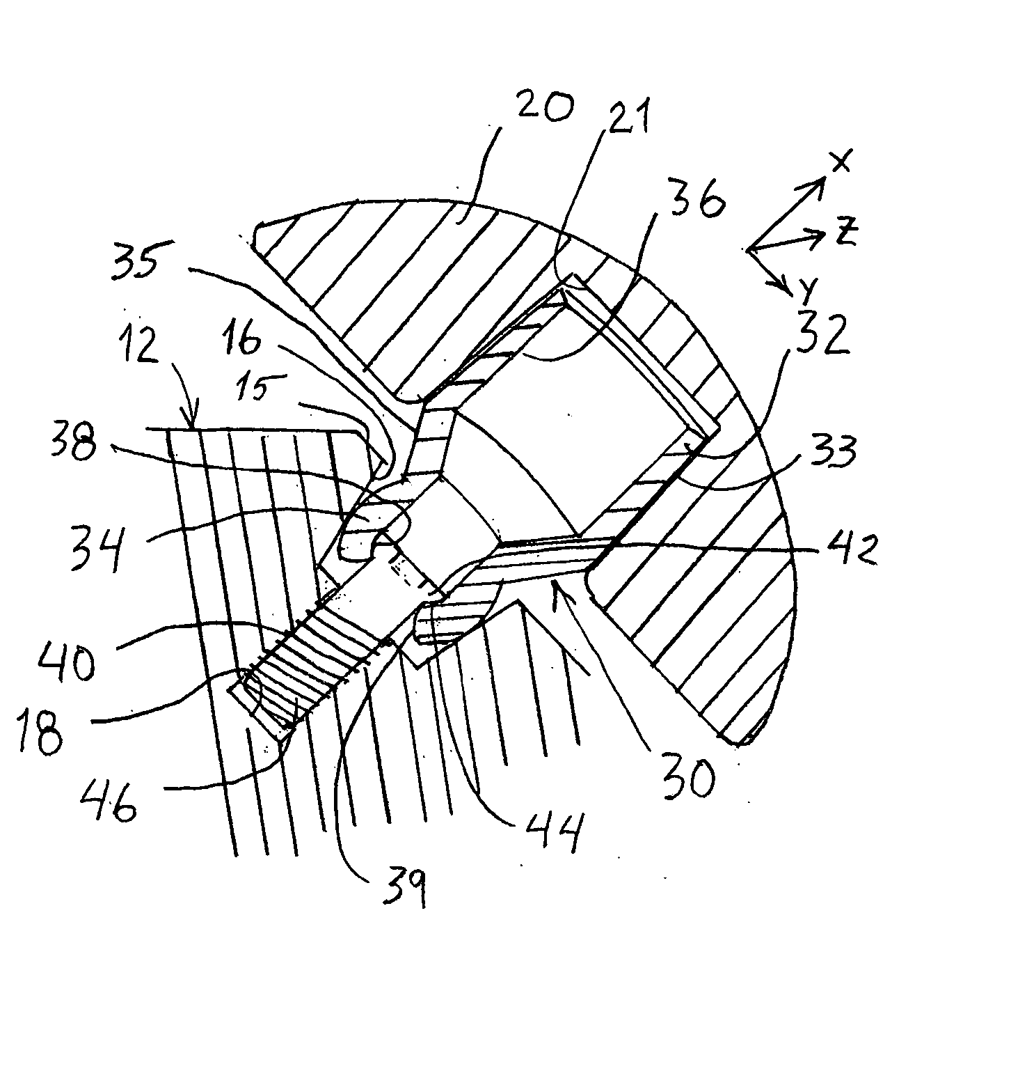
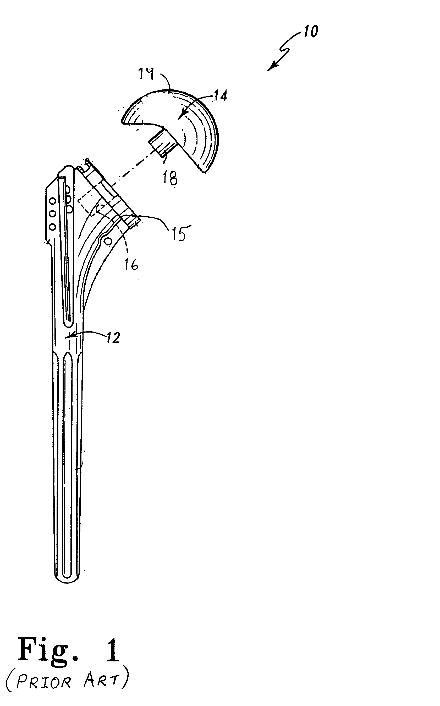
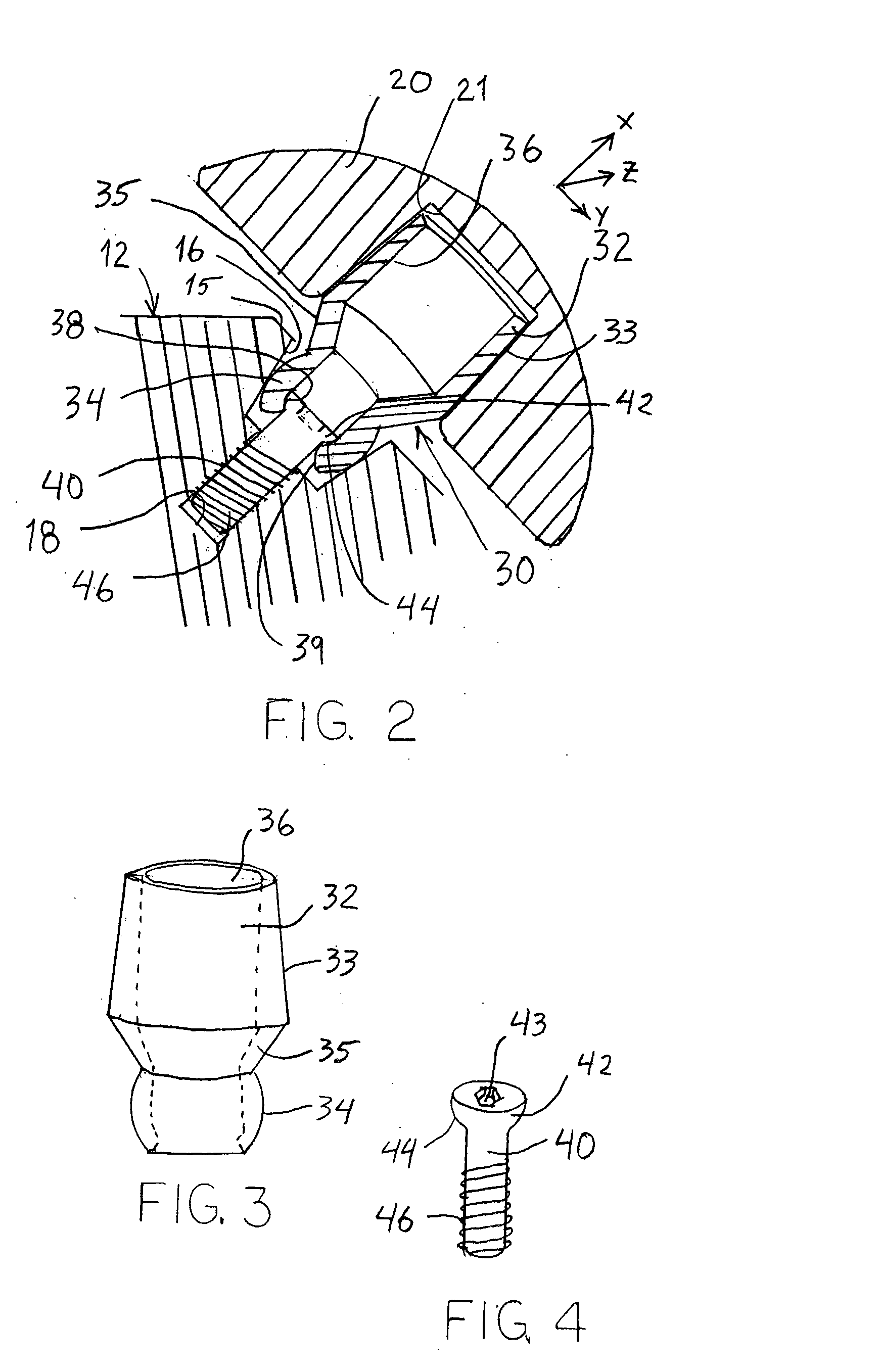
[0023] A typical joint prosthesis of the prior art is illustrated in FIG. 1. The prosthesis 10 is the humeral component of a shoulder prosthesis that can be implanted in the humerus bone for articulating engagement with the natural glenoid or with a glenoid prosthesis. The prosthesis 10 includes a stem 12 configured to be implanted within the humerus bone in a conventional manner. The stem 12 forms a platform ...


PUM


Abstract

A joint prosthesis includes a head component that is engaged to a bone stem through a mounting element. The mounting element is configured for articulating engagement with the stem to permit angular positioning of the head component in multiple degrees of freedom. The mounting element is fastened to the stem by a press-fit engagement and a separate mechanical fastener.

Description

BACKGROUND OF THE INVENTION [0001] The present invention relates to joint prosthesis, and particularly to prosthesis having an articulating head component. More specifically, the invention relates to a system for achieving infinitely variable positions for the head component relative to a bone engaging portion of the prosthesis. [0002] Repair and replacement of human joints, such as the knee, shoulder, elbow and hip, has become a more and more frequent medical treatment. Longer life spans mean that the joints endure more wear and tear. More sports activities mean greater likelihood of serious joint injuries. Treatment of injuries, wear and disease in human joints has progressed from the use of orthotics to mask the problem, to fusion of the joint, to the use of prostheses to replace the damaged joint component(s). [0003] As the success rate for total or partial joint replacements has increased, so too has the need for modularity and universality in the joint prosthesis. Patient vari...

Claims


Application Information

Patent Timeline
IPC IPC(8): A61F2/00A61F2/02A61B17/56A61F2/30A61F2/32A61F2/40
CPCA61F2/4014A61F2002/30332A61F2002/30433A61F2002/30538A61F2002/30604A61F2250/0006A61F2002/404A61F2002/4044A61F2220/0033A61F2220/0041A61F2002/30772A61F2002/4037
Inventor ONDRLA, JEFFWILLIAMS, GERALD ROSS JR.IANNOTTI, JOSEPH PATRICKGIBBONS, PAULCLARK, JAMES EDWARD
Owner DEPUY SYNTHES PROD INC
Why Eureka
Try Eureka