Heat pipe structure

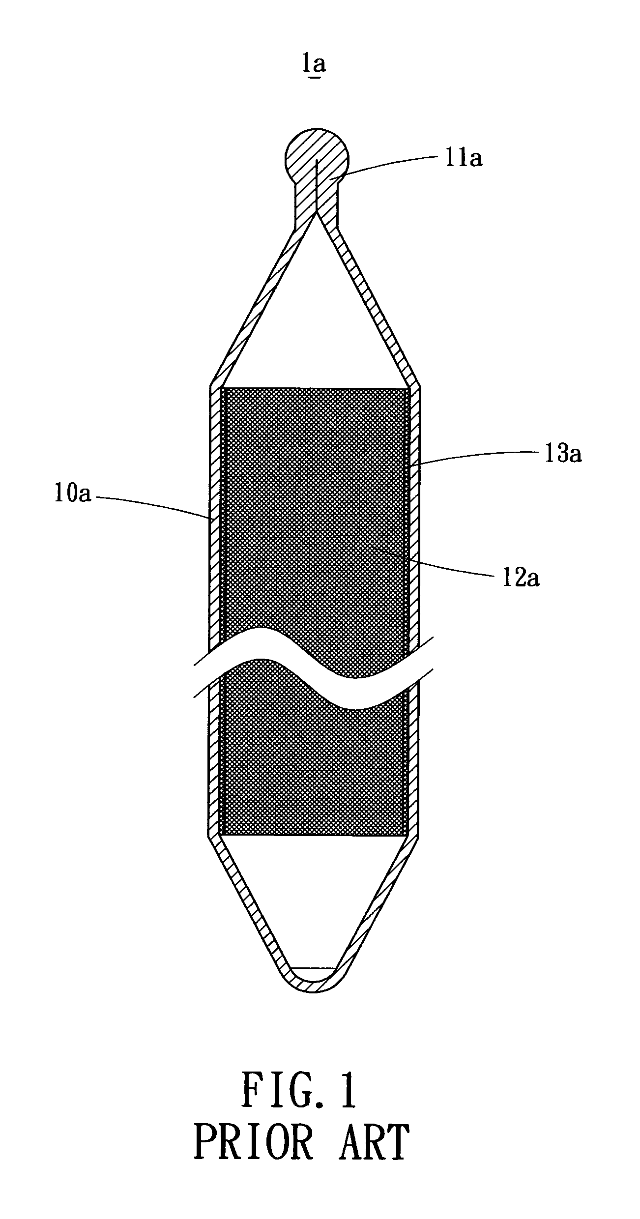
a technology of heat pipe and end portion, which is applied in the direction of lighting and heating apparatus, basic electric elements, and semiconductor devices, can solve the problem that the end portion of the conventional heat pipe cannot be used, and achieve the effect of reducing the limitation of use and facilitating the dissipation of heat pip

Inactive Publication Date: 2005-07-07
HSU HUL CHUN
View PDF12 Cites 3 Cited by
  • Summary
  • Abstract
  • Description
  • Claims
  • Application Information

AI Technical Summary

Benefits of technology

[0005] The present invention provides a heat pipe structure of which the wick structure is attached to the inner surface of the end portion thereof such that the heat pipe can be used to contact a heat source with the end portion for dissipation. Therefore, more availability for dissipating of the heat pipe can be obtained and further the limitation in use can be reduced too.

Problems solved by technology

Therefore, conventional heat pipes can not use the end portion to contact the heat sink or heat source for dissipating.

Method used


Image

  • Heat pipe structure
  • Heat pipe structure
  • Heat pipe structure

Examples


Embodiment Construction

[0019] Reference will now be made in detail to the preferred embodiments of the present invention, examples of which are illustrated in the accompanying drawings. Wherever possible, the same reference numbers are used in the drawings and the description to refer to the same or like parts.

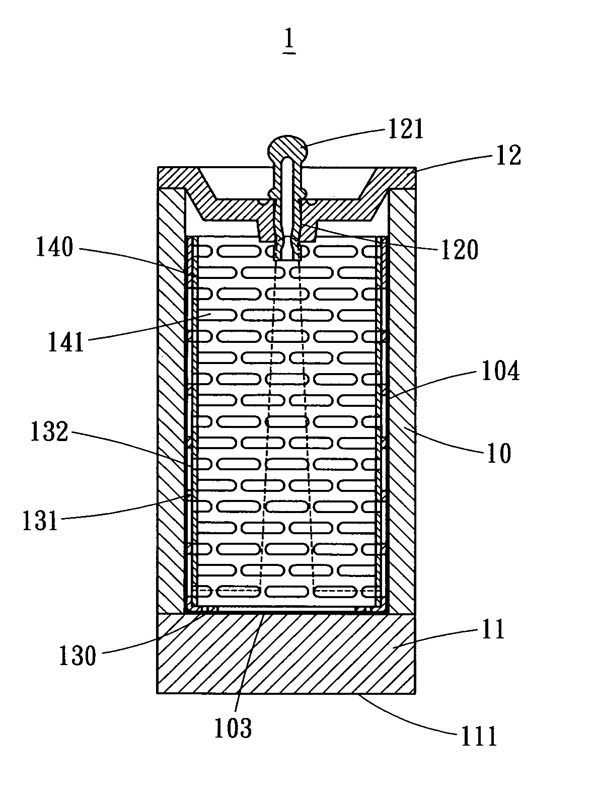
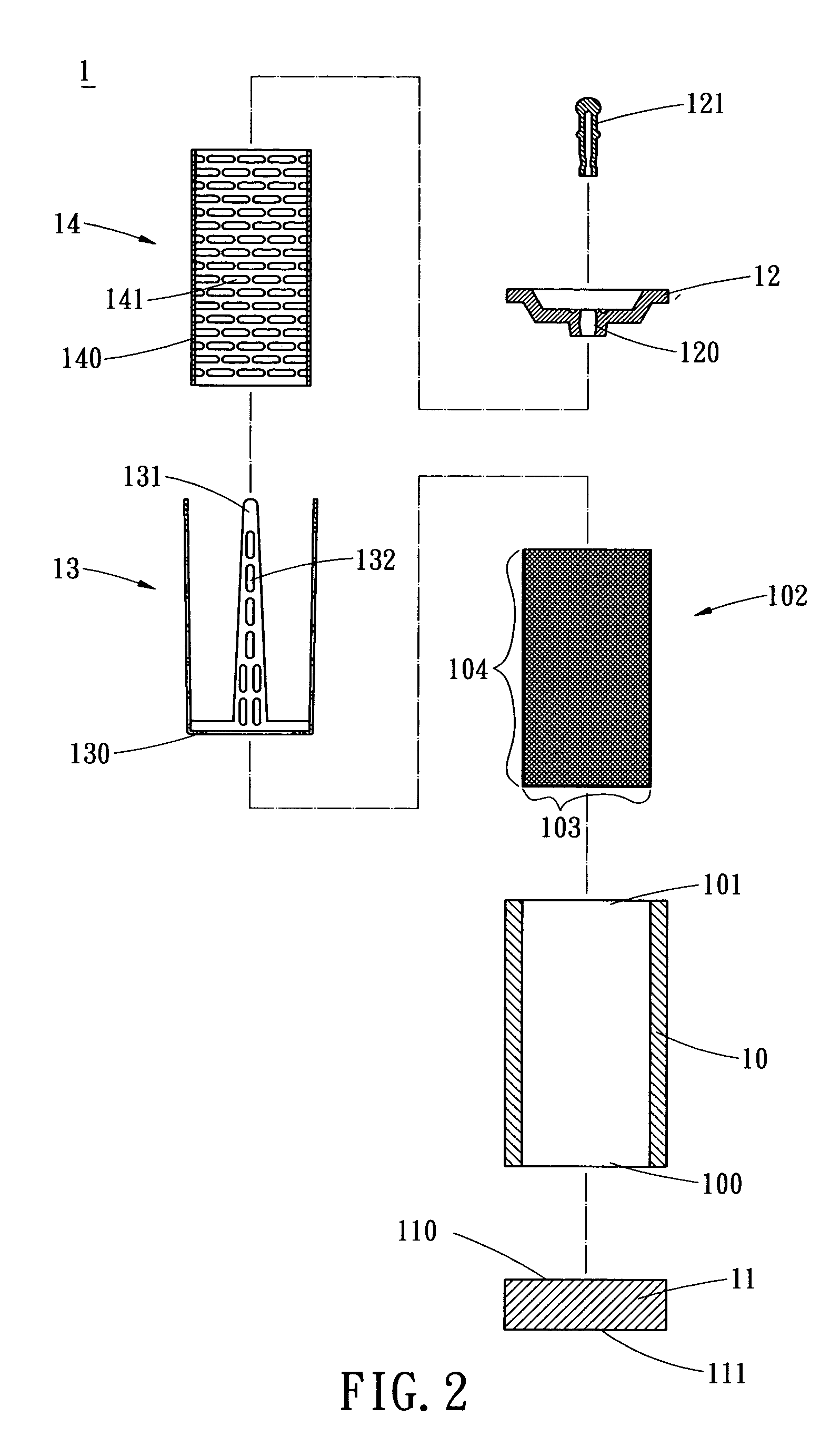
[0020]FIGS. 2 and 3 illustrate cross sectional views of the exploded and assembled heat pipe the present invention, respectively. As shown, the heat pipe 1 includes a tubular member 10, a bottom portion 11, a lid 12, a first support member 13 and a second support member 14.

[0021] The tubular member 10 is hollow and includes two openings 100, 101 at both ends connecting to the bottom portion 11 and the lid 12, respectively. The bottom portion 11 has an inner surface 110 and an outer surface 111. The inner surface 110 can be formed as a plane surface, a conical surface, a convex surface or a concave surface. Further, the bottom portion 11 can be integratedly formed with the tubular member 10. The li...


PUM


Abstract

A heat pipe structure includes a tubular member, and a wick structure having a base portion formed at one end of the tubular member and a surrounding portion extending from the base portion for attaching to an interior wall of the tubular member. Therefore, an end portion of a heat pipe can be used to contact a heat source for dissipation to provide more efficient dissipation and prevent from limitation of use.

Description

BACKGROUND OF THE INVENTION [0001] The present invention relates to a heat pipe structure, and more particular, to a heat pipe structure of which a wick structure is attached to an inner surface of an end portion thereof such that a heat pipe can be used to contact a heat source with the end portion for dissipation. [0002] Heat pipes have been commonly used for dissipating heat generated by electronic products. The heat pipes have high thermal conducting ability, high thermal transmission, high thermal conductivity, light weight, non-mobile device, simple structure and versatile applications. [0003] As shown in FIG. 1, the conventional heat pipe structure 1a includes two conoid ends converged from the tubular member 10a. One of the conoid end 11a is formed by soldering after a wick structure 13a is attached to an interior wall of the tubular member by a supporting member 12a. The wick structure 13a is includes a screen mesh with capillary function which is advantageous for transmiss...

Claims


Application Information

Patent Timeline
Patent Type & Authority Applications(United States)
IPC IPC(8): F28D15/00F28D15/02F28D15/04H01L23/427
CPCF28D15/0283F28D15/046H01L23/427H01L2924/0002H01L2924/00
Inventor HSU, HUL CHUN
Owner HSU HUL CHUN
Why Eureka
Try Eureka