
Method and tool for making enhanced heat transfer surfaces

Active Publication Date: 2005-07-07
WIELAND WERKE AG
View PDF67 Cites 33 Cited by
  • Summary
  • Abstract
  • Description
  • Claims
  • Application Information

AI Technical Summary

Benefits of technology

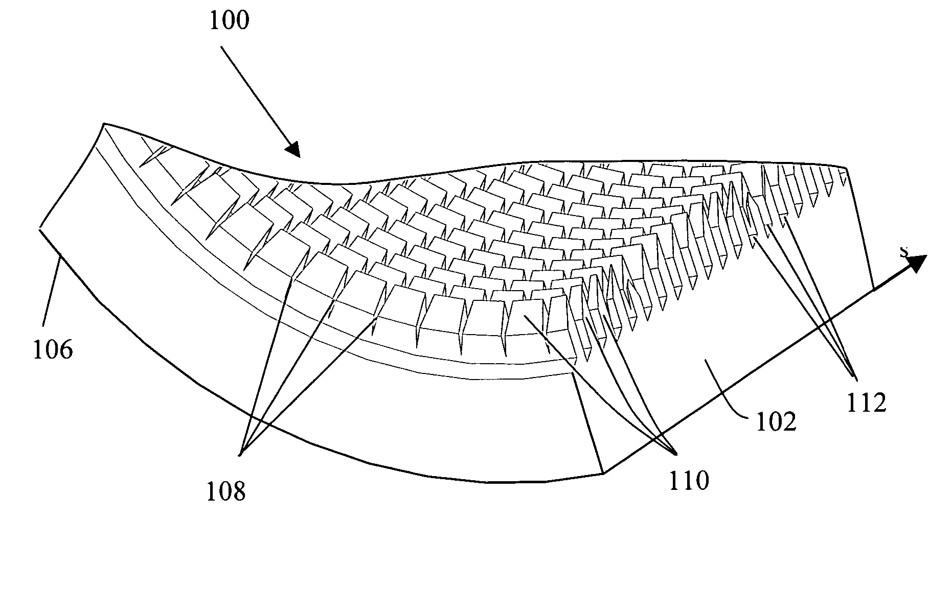
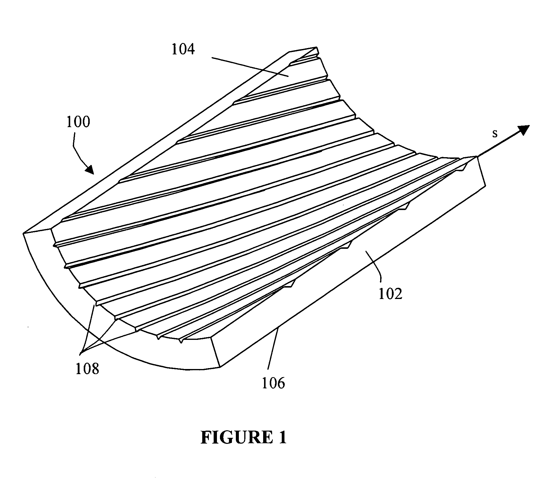
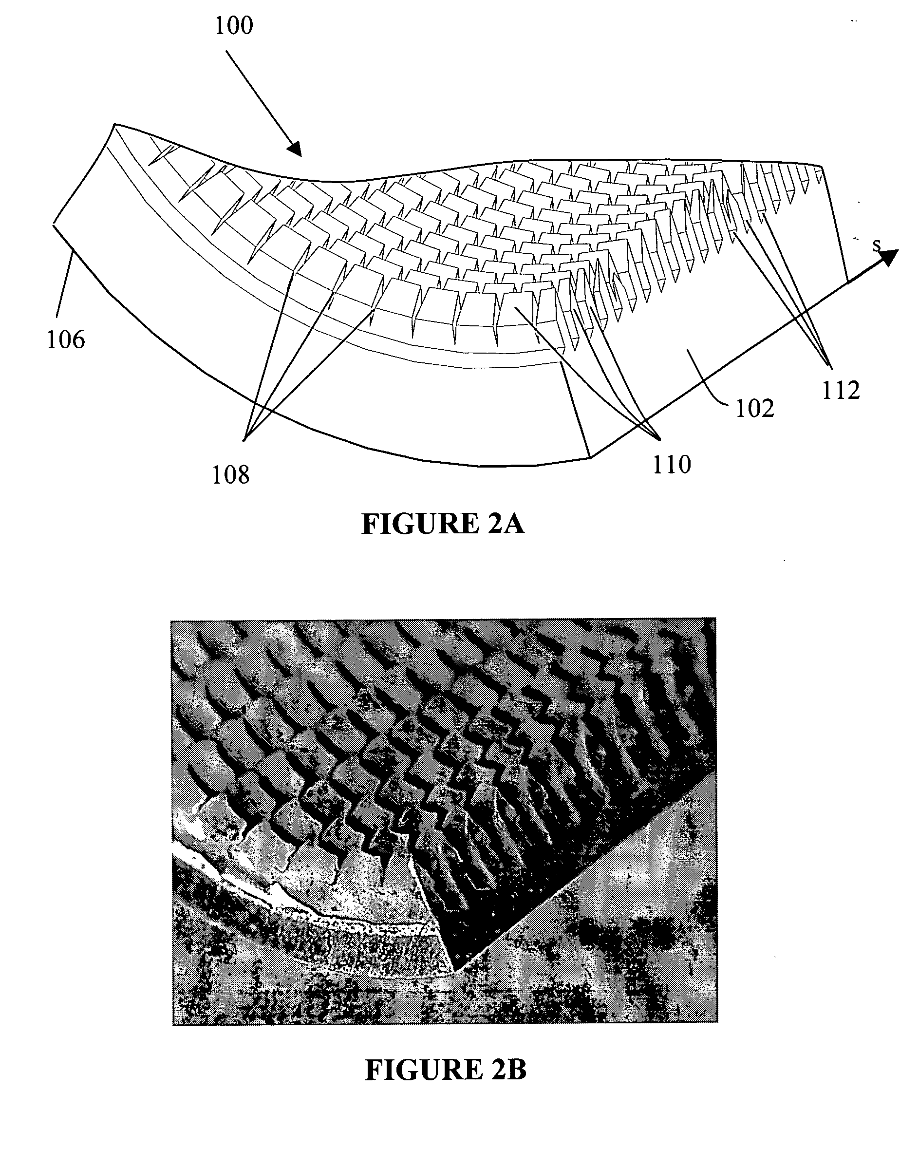
[0009] Embodiments of the invention provide an improved heat transfer surface, such as may be formed on a tube, and a method of formation thereof that can be used to enhance heat transfer performance of tubes used in at least all of the above-referenced applications (i.e., flooded evaporators, falling film evaporators, spray evaporators, absorption chillers, condensers, direct expansion coolers and single phase coolers and heaters, used in the refrigeration, chemical, petrochemical and food-processing industries). The surface is enhanced with a plurality of cavities that significantly decrease the transition time to move from one phase to the next, for example to move from boiling to evaporation. The cavities create additional paths for fluid flow within the tube and thereby enhance turbulence of heat transfer mediums flowing within the tube. Protrusions creating cavities also provide extra surface area for additional heat exchange. Tests show that performance of tubes according to embodiments of the invention is significantly enhanced.
[0010] Certain embodiments of the invention include a method for using a tool, which can be easily added to existing manufacturing equipment, having a mirror image of a pattern of grooves desired to formed on the tube surface. Certain embodiments of the invention also include using a tool, which also can be easily added to existing manufacturing equipment, having a cutting edge to cut through the surface of tube and a lifting edge to lift the surface of the tube to form protrusions. In this way, protrusions are formed without removal of metal from the inner surface of the tube, thereby eliminating debris which can damage the equipment in which the tubes are used. Finally, certain embodiments of the invention include using a tool, which also can be easily added to existing manufacturing equipment, for flattening or bending the tips of the protrusions, such as a mandrel. The grooves, protrusions and flattened tips on the tube surface can be formed in the same or a different operation. In certain embodiments of the invention, the three tools are secured on a single shaft and the tube surfaces are formed in one operation.

Problems solved by technology

However, the voids or cells formed by the above-mentioned methods are small and impurities contained in the boiling liquid may clog them so that the heat transfer performance of the surface is impaired.
Additionally, since the voids or cells formed are non-uniform in size or dimension, the heat transfer performance may vary along the surface.
Furthermore, known heat transfer tubes incorporating boiling or evaporating surfaces often require multiple steps or passes with tools to create the final surface.

Method used


Image

  • Method and tool for making enhanced heat transfer surfaces
  • Method and tool for making enhanced heat transfer surfaces
  • Method and tool for making enhanced heat transfer surfaces

Examples


Embodiment Construction

[0048] It should be understood that a tube in accordance with this invention is generally useful in, but not limited to, any application where heat needs to be transferred from one side of the tube to the other side of the tube, such as in multi-phase (both pure liquids or gases or liquid / gas mixtures) evaporators and condensers. While the following discussion provides desirable dimensions for a tube of this invention, the tubes of this invention are in no way intended to be limited to those dimensions. Rather, the desirable geometries of the tube will depend on many factors, not the least important of which are the properties of the fluid flowing through the tube. One skilled in the art would understand how to alter the geometry of the surfaces of the tube to maximize heat transfer used in various applications and with various fluids. Furthermore, although the drawings show the surface as it would be when found on the inner surface of a tube, it should be understood that the surfac...


PUM

PropertyMeasurementUnit
Thicknessaaaaaaaaaa
Depthaaaaaaaaaa

Abstract

The invention relates to enhanced heat transfer surfaces and methods and tools for making enhanced heat transfer surface. Certain embodiments include a boiling surface that include a plurality of primary grooves, protrusions and secondary grooves to form boiling cavities. The boiling surface may be formed by using a tool for cutting the inner surface of a tube. The tool has a tool axis and at least one tip with a cutting edge and a lifting edge. Methods for making a boiling surface are also disclosed, including cutting through the inner surface of a tube to form primary grooves, then cutting and lifting the inner surface to form protrusions and secondary grooves.

Description

CROSS REFERENCE TO RELATED APPLICATIONS [0001] This application claims the benefit of U.S. application Ser. No. 60 / 514,418, filed on Oct. 23, 2003 and claims priority to U.S. application Ser. No. 10 / 458,398, filed Jun. 10, 2003, which claims the benefit of U.S. application Ser. No. 60 / 387,328, filed Jun. 10, 2002.BACKGROUND [0002] 1. Field of the Invention [0003] The invention relates generally to enhanced heat transfer surfaces and a method of and tool for forming enhanced heat transfer surfaces. [0004] 2. General Background of the Invention [0005] The invention relates to enhanced heat transfer surfaces that facilitate heat transfer from one side of the surface to the other. Heat transfer surfaces are commonly used in equipment such as, for example, flooded evaporators, falling film evaporators, spray evaporators, absorption chillers, condensers, direct expansion coolers, and single phase coolers and heaters, used in the refrigeration, chemical, petrochemical and food-processing i...

Claims


Application Information

Patent Timeline
IPC IPC(8): B21C37/20B21D31/00F28F13/18
CPCB21C37/20B21C37/207B21D31/00F28F13/187F28F1/42F28F1/422F28F1/40B21J5/068Y10T83/0304
Inventor THORS, PETURZOUBKOV, NIKOLAI
Owner WIELAND WERKE AG
Learn More