Supercharge Your Innovation With Domain-Expert AI Agents!

Optical pickup device and optical disc apparatus

a pickup device and optical disc technology, applied in the field of optical elements, can solve problems such as noise generation

Inactive Publication Date: 2005-07-07
SONY CORP
View PDF6 Cites 19 Cited by
  • Summary
  • Abstract
  • Description
  • Claims
  • Application Information

AI Technical Summary

Benefits of technology

[0015] Through the shielding means, the optical path can be limited such that light is not incident in unnecessary portions outside the prescribed optical path.

Problems solved by technology

As a result, stray light occurs, becoming light returning to the semiconductor laser or distorting the shape of the focused spot of laser light, and as a result generating noise or causing other problems.

Method used


Image

  • Optical pickup device and optical disc apparatus
  • Optical pickup device and optical disc apparatus
  • Optical pickup device and optical disc apparatus

Examples


Embodiment Construction

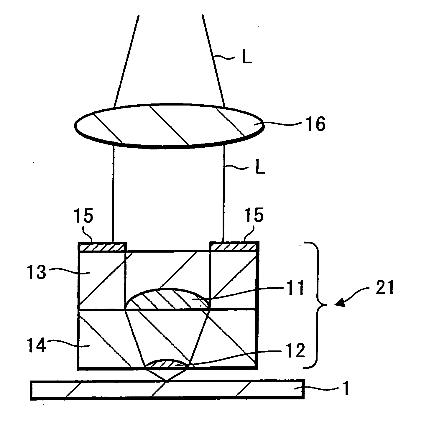
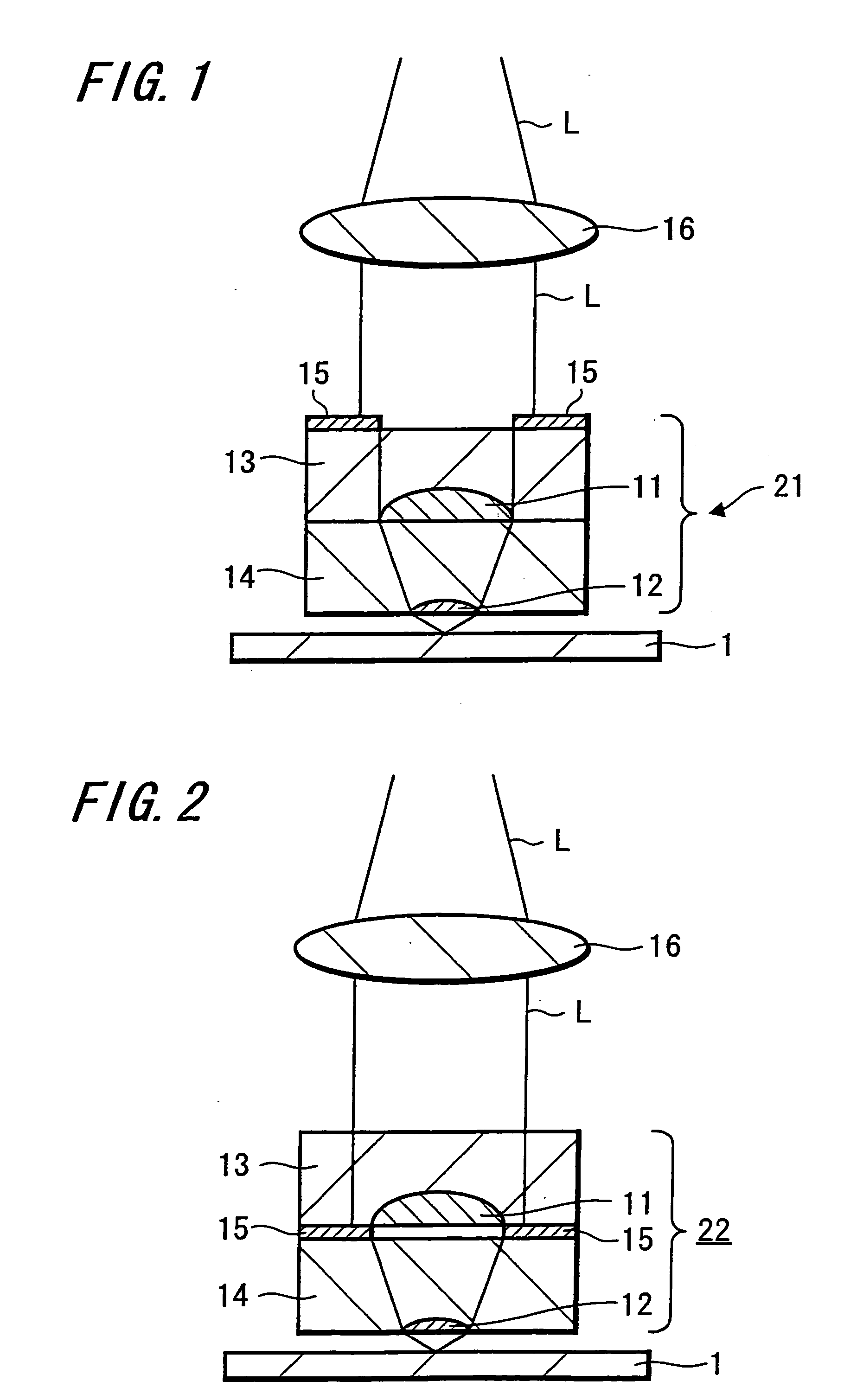
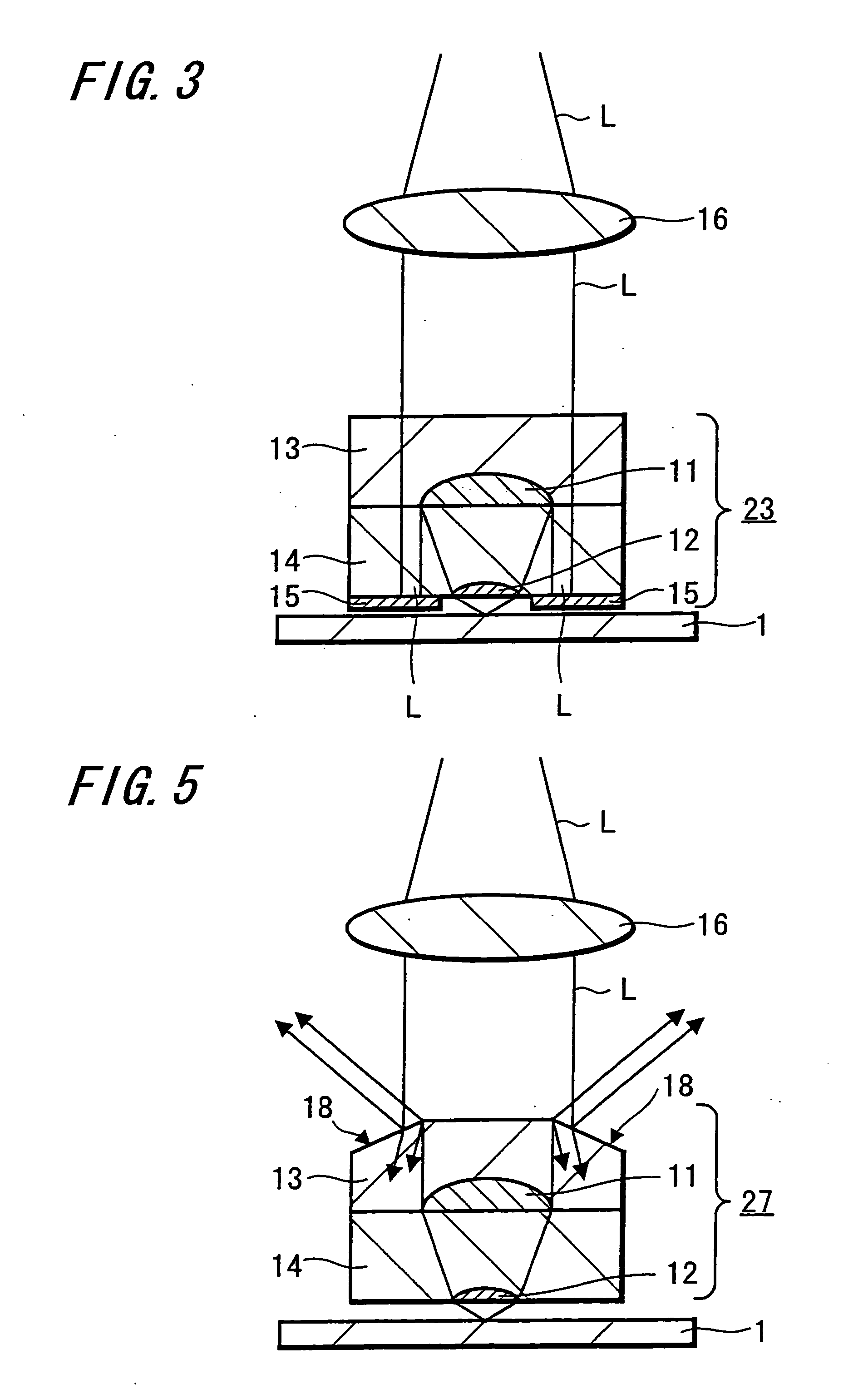
[0030] This invention relates to an optical element comprising one or more substrates which are transparent to incident light, each comprising a lens substrate formed by embedding, in a substrate transparent to incident light, a lens of material with a higher refractive index than that of the substrate; one among the one or more substrates is formed with shielding means, in the surface of light incidence or in the surface of light emission, to limit the optical path such that incident light propagates only within a prescribed optical path through the action of either reflection, refraction, absorption, or dispersion.

[0031] The above-described optical element of this invention is configured by stacking a plurality of lens substrates.

[0032] A method of manufacture of an optical element of this invention is a method of formation of an optical element comprising one or more substrates, transparent to incident light, each comprising a lens substrate formed by embedding, in a substrate ...


PUM

PropertyMeasurementUnit
refractive indexaaaaaaaaaa
optical pathaaaaaaaaaa
reflectionaaaaaaaaaa

Abstract

An optical pickup device and optical disc apparatus of the present invention include an optical element that prevents the incidence of light on unnecessary portions of the optical element so that stray light and noise are eliminated. The optical element include at least one substrate having a plurality of lens substrates that have embedded lenses made of a material with a higher refractive index than the at least one substrate. A shielding means limits the optical path so that incident light propagates only within a prescribed optical path formed on a light incidence-side or emission-side surface of one of the lens substrates. In addition, the shielding means is formed from an absorptive or reflective film placed in a region outside the prescribed optical path or through machining the region outside the prescribed optical path.

Description

TECHNICAL FIELD [0001] This invention relates to an optical element comprising a lens substrate, in which a high-refractive-index lens is embedded in a substrate, and a manufacturing method therefor. BACKGROUND ART [0002] Apertures are important components of optical pickups and other optical apparatuses which, by limiting the optical path, eliminates stray light and other external disturbances. [0003]FIG. 14 shows the conventional configuration of an optical head using an optical element proposed in, for example, Japanese Patent Application No. 2000-132897, Japanese Patent Application No. 2000-189730, or similar. [0004] This optical element (lens element) 70 is configured by stacking a first lens substrate 73, in which a first objective lens 71 is embedded in a transparent substrate, and a second lens substrate 74, in which a second objective lens 72 is embedded in a transparent substrate. [0005] The first and second objective lenses 71 and 72 have higher refractive indices than th...

Claims


Application Information

Patent Timeline
Patent Type & Authority Applications(United States)
IPC IPC(8): G02B3/00G02B13/00G02B5/00G11B7/135
CPCG11B7/1374G11B7/139G11B7/1387G11B7/1378G11B7/1372G11B7/1381G02B3/00G02B5/00
Inventor YAMADA, MASAHIROMIURA, TAKAHIROKANAZAWA, TAKAKIYOWATANABE, TETSUAOKI, SUNAO
Owner SONY CORP
Features
  • R&D
  • Intellectual Property
  • Life Sciences
  • Materials
  • Tech Scout
  • Unparalleled Data Quality
  • Higher Quality Content
  • 60% Fewer Hallucinations
Learn More