
Valve device

a valve element and valve element technology, applied in the direction of valve details, valve arrangement, thin material handling, etc., can solve the problems of increasing the torque required of the motor drive part, affecting the stability the difficulty of stable opening/closing so as to achieve stable open/close control of the valve element, and the torque required in the motor drive part is restricted.

Active Publication Date: 2005-07-14
SANKYO SEIKI MFG CO LTD
View PDF4 Cites 14 Cited by
  • Summary
  • Abstract
  • Description
  • Claims
  • Application Information

AI Technical Summary

Benefits of technology

[0009] In view of the problems described above, it is a primary object and advantage of the present invention to provide a valve device in which a valve element performs opening and closing operations of a flow path for various types of fluid with a simple construction, which is capable of restricting the variation of the torque required in the motor drive part and realizing a stable opening / closing operation of the valve element.
[0010] In order to achieve the above object and advantage, according to an embodiment of the present invention, there is provided a valve device including a main body case to which an inflow pipe allowing fluid to flow in and an outflow pipe allowing fluid to flow out are connected, a fluid flow path formed inside of the main body case for allowing the fluid flown in from the inflow pipe to flow to the outflow pipe, a valve element which is disposed inside of the main body case to open or close an outflow aperture part of the main body case which is in communication with the outflow pipe, a valve element drive means having a motor drive part for opening or closing the valve element, and a magnetic drive means included in the valve element drive means for generating an urging force to move the valve element in at least one of an open direction or a closed direction by using at least one of a magnetic attractive force and a magnetic repulsive force generated with permanent magnets.
[0011] In accordance with the embodiment of the present invention, an urging force in the open direction or in the closed direction is applied to the valve element by the magnetic drive means. Therefore, the opening / closing of the outflow aperture part can be performed by the valve element under the state that the mechanical connection between the valve element and the motor drive part of the valve element drive means is not performed. Accordingly, the variation of the torque required in the motor drive part is restricted even when a load such as the sliding resistance or the fluid pressure applied to the valve element varies. As a result, stable open / close control of the valve element is attained even when the motor drive part generating a large torque is not used.
[0012] In accordance with an embodiment of the present invention, the valve element drive means is preferably constructed such that a magnetic force generated by the magnetic drive means is interchanged between an attractive force and a repulsive force to reverse the direction of the urging force to drive the valve element in the open direction or in the closed direction.
[0013] In accordance with an embodiment of the present invention, the valve element drive means is provided with a rotary member which faces the valve element, and the magnetic drive means is provided with a rotation side magnet part which includes an N-pole and an S-pole at different angle positions of the rotary member and a valve element side magnet part. The magnetic drive means is constructed such that a magnetic force generated between the rotation side magnet part and the valve element side magnet part is interchanged between an attractive force and a repulsive force to drive the valve element in the open direction or in the closed direction. According to the construction described above, the movement of the valve element in the open direction and the closed direction can be performed under the state that the mechanical connection between the valve element and the rotary member is not performed. Accordingly, the variation of the torque required in the motor drive part is restricted even when a load such as the sliding resistance or the fluid pressure applied to the valve element varies. As a result, stable open / close control of the valve element is attained even when the motor drive part generating a large torque is not used.
[0014] In accordance with an embodiment of the present invention, the valve element is preferably disposed so as to move in an open position apart from the outflow aperture part and in a closed position where the outflow aperture part is closed. According to the construction described above, since the valve element performs the opening / closing of the fluid aperture part without sliding motion on the fluid aperture part, the degree of surface roughness, the flatness, time degradation of the sliding face or the like do not affect the opening / closing operation. Therefore, stable open / close control of the valve element is attained. In addition, in the embodiment of the present invention, the rotary member and the valve element are magnetically connected to each other and they are mechanically separated from each other. Therefore, even when a large fluid pressure is applied to the valve element, the affection to the torque required in the motor drive part can be restricted.

Problems solved by technology

Further, the sliding resistance increases due to the aged deterioration of the sliding face and therefore the required torque of the motor drive part increases at a starting time or at an opening / closing operation time.
Accordingly, the stable opening / closing control of the valve element becomes difficult.
Especially when the fluid pressure is high, the required torque of the motor drive part increases and therefore, a stable opening / closing control of the valve element becomes difficult unless a motor drive part with a large rotating torque is used.

Method used


Image

  • Valve device
  • Valve device
  • Valve device

Examples


Embodiment Construction

[0027] A valve device in accordance with an embodiment of the present invention will be described below with reference to the accompanying drawings.

Entire Construction

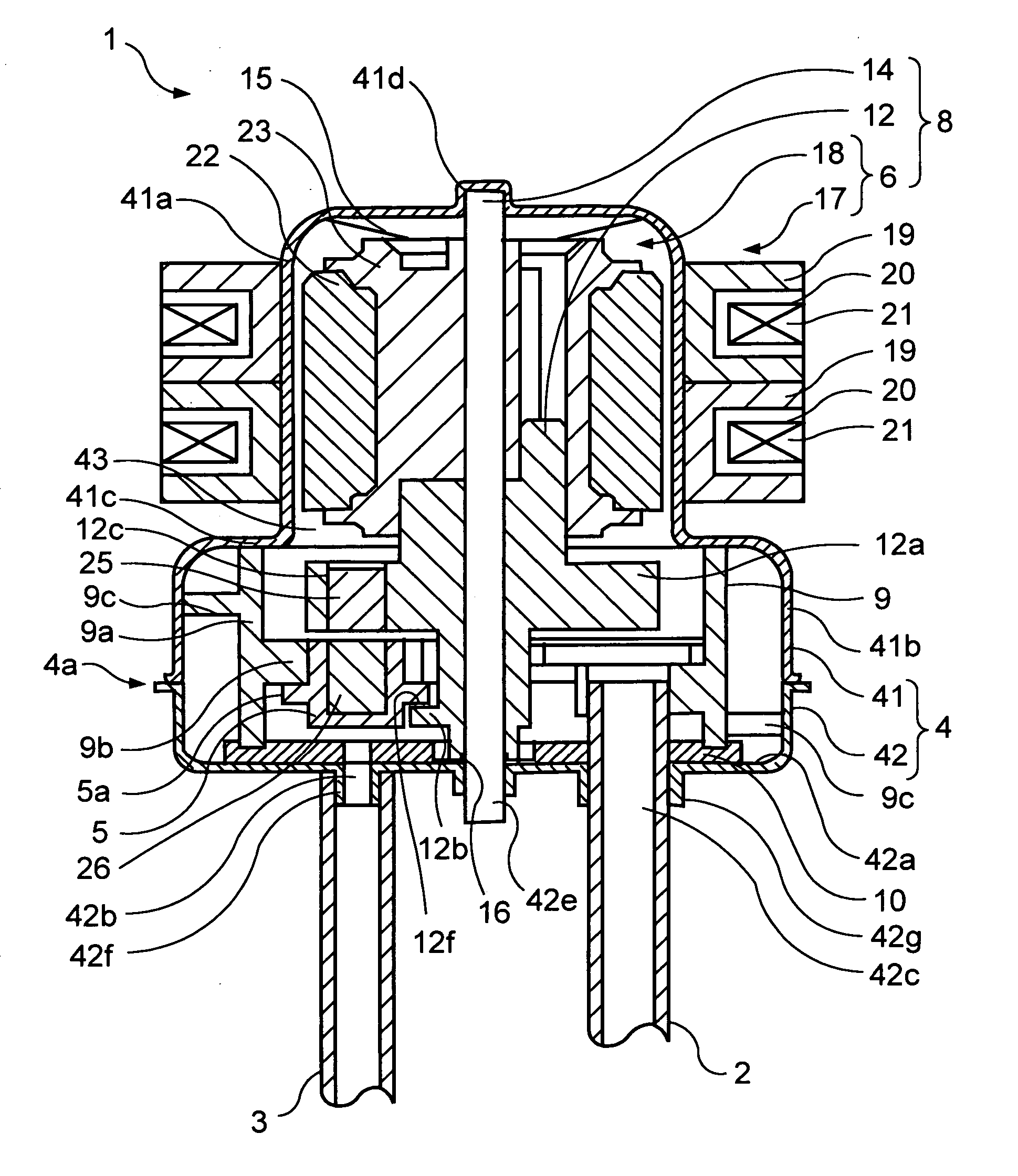
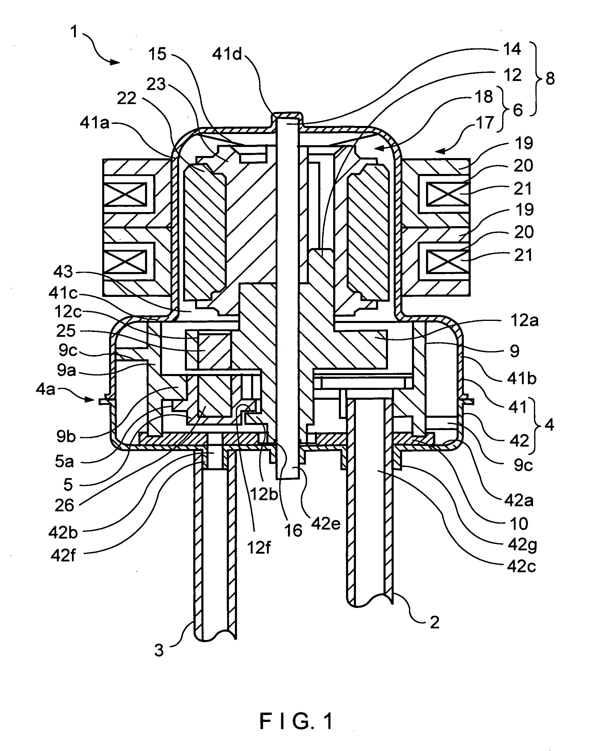
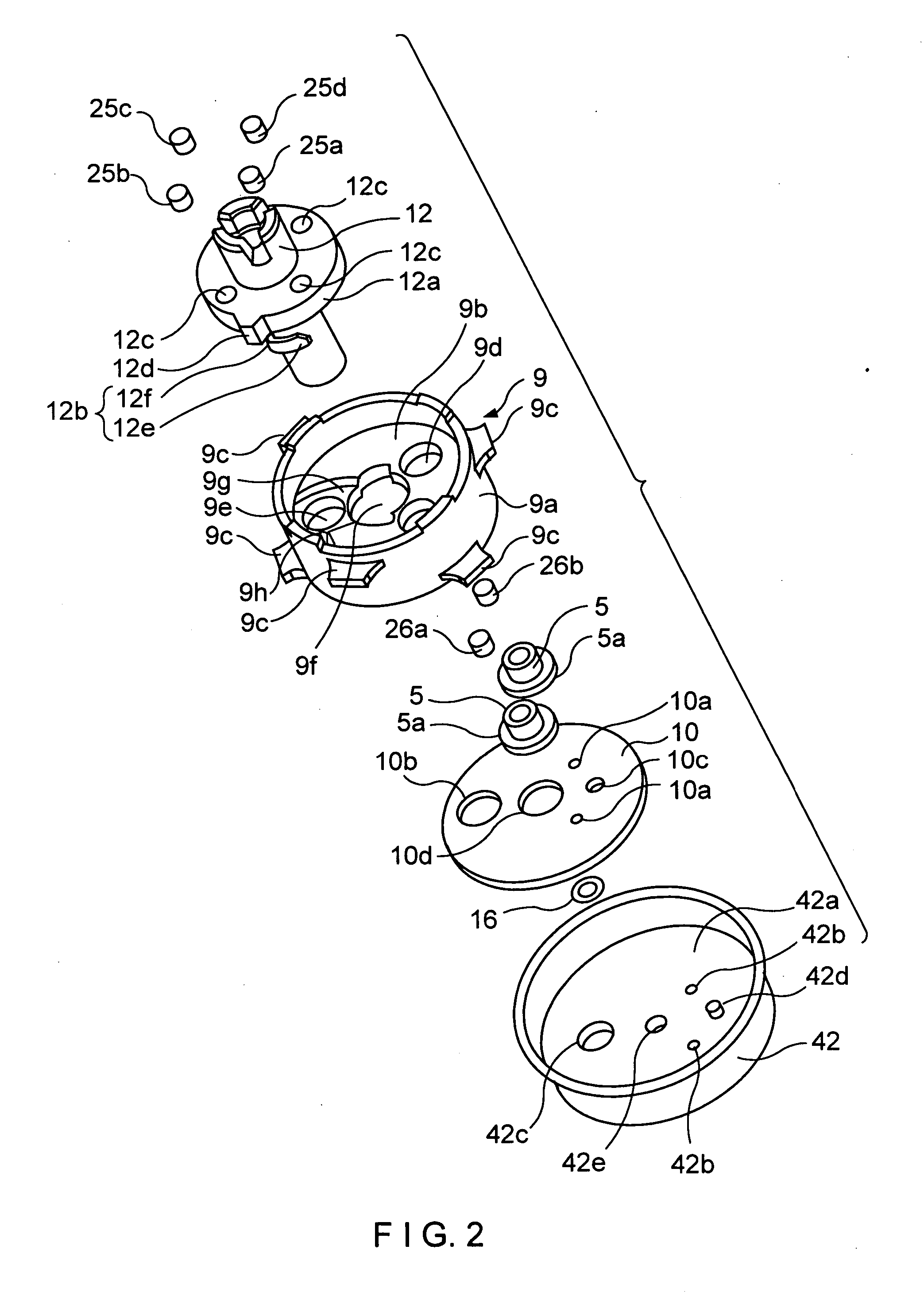
[0028]FIG. 1 is a longitudinal cross-sectional view showing a valve device in accordance with an embodiment of the present invention, in which valve elements are located at an open position. FIG. 2 is an exploded perspective view showing a principal portion of the valve device shown in FIG. 1.

[0029] The valve device 1 in accordance with an embodiment of the present invention is a valve device for opening or closing, for example, a flow path of refrigerant in a refrigerator to perform temperature control of a refrigerating compartment that is in communication with the flow path. The valve device 1 includes a main body case 4, valve elements 5 and a valve element drive means 8. The main body case 4 within which a fluid flow path 43 is formed is constructed such that the main body case 4 is connected to a inflow pipe ...


PUM


Abstract

A valve device includes a main body case to which an inflow pipe and an outflow pipe are connected, a valve element which is disposed inside of the main body case to open or close an outflow aperture part of the main body case, a motor for moving the valve element in an open direction and a closed direction, a valve element drive means which is driven by the motor and includes a rotary member rotated by the motor and a rotation side permanent magnet mounted in the rotary member, a valve element side permanent magnet mounted in the valve element, and a holding member which movably holds the valve element. The valve element is urged in the open direction or the closed direction by a magnetic attractive force or a magnetic repulsive force generated between the rotation side permanent magnet and the valve element side permanent magnet.

Description

CROSS-REFERENCE TO RELATED APPLICATIONS [0001] This application claims priority to Japanese Application No. 2003-422454 filed Dec. 19, 2003, which is incorporated herein by reference. BACKGROUND OF THE INVENTION [0002] a) Field of the Invention [0003] The present invention relates to a valve device in which a valve element is operated to perform opening / closing of a flow path for various types of fluid. More specifically, the present invention relates to a valve element opening / closing mechanism for a valve device. [0004] b) Description of the Related Art [0005] A valve device has been known which performs a temperature control in a chamber which is in communication with a flow path by means of opening or closing the flow path for various types of fluid such as refrigerant for a refrigerator or an air conditioner. An inflow pipe for allowing the fluid to flow in and an outflow pipe allowing the fluid to flow out are connected to the valve device. The valve device includes a main bod...

Claims


Application Information

Patent Timeline
Patent Type & Authority Applications(United States)
IPC IPC(8): F16K11/072F16K31/06F16K31/02F16K31/04F16K31/08
CPCF16K31/045F16K31/042Y10T137/86863F16K31/06F16K31/02
Inventor OZAWA, SHIGERUHARA, TETSUHIKO
Owner SANKYO SEIKI MFG CO LTD
Learn More