Electric power steering device
a technology of electric power steering and steering wheel, which is applied in the direction of electric steering, power driven steering, vehicle components, etc., can solve the problems of driver discomfort, and achieve the effects of reducing discomfort felt by drivers, accurately detecting reverse steering, and increasing transfer gain
- Summary
- Abstract
- Description
- Claims
- Application Information
AI Technical Summary
Benefits of technology
Problems solved by technology
Method used
Image
Examples
first embodiment
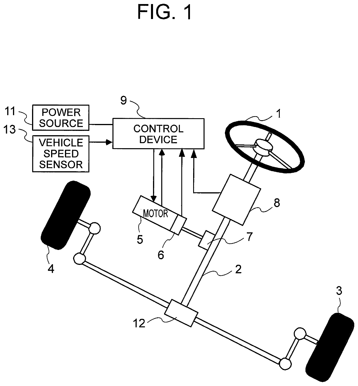
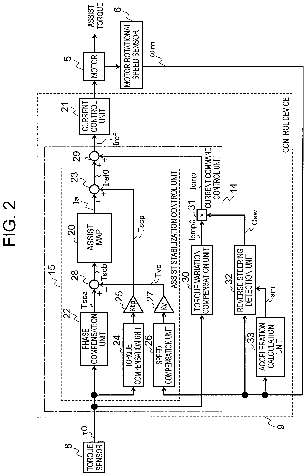
[0044]FIG. 1 is a configuration diagram for illustrating an electric power steering device according to a first embodiment of the present invention. In FIG. 1, the electric power steering device includes a steering wheel 1, a steering shaft 2, wheels 3 and 4, a motor 5, a motor rotational speed sensor 6, a motor deceleration gear 7, a torque sensor 8, a control device 9, a power source 11 being a battery, a rack and pinion gear 12, and a vehicle speed sensor 13.
[0045]Next, a description is given of an operation of the electric power steering device with reference to FIG. 1. A steering torque applied to the steering wheel 1 by a driver (not shown) is transmitted to a rack via the rack and pinion gear 12 through intermediation of a torsion bar of the torque sensor 8 and the steering shaft 2, to thereby turn the wheels 3 and 4.
[0046]The motor 5 is coupled to the steering shaft 2 via the motor deceleration gear 7. Further, an output torque generated by the motor 5 is transmitted to the ...
second embodiment
[0114]Now, a description is given of an electric power steering device according to a second embodiment of the present invention with reference to FIG. 12. In this case, a difference from the first embodiment is that a jerk correction term is added to setting of the speed threshold ε in Step S02 of FIG. 12, and other parts are the same as those of the first embodiment. Thus, a description thereof is omitted, and only the difference is described.
[0115]As shown in FIG. 6 and FIG. 7, when the motor rotational acceleration am is changing, a derivative of the motor rotational acceleration am, namely, a motor rotational jerk jm is used to correct the speed change prediction amount Δω1 by the following expression, to thereby be able to detect reverse steering at a more accurate timing.
Δω1=Tkk×|am1|+½×|jm|×Tkk2
[0116]When it is assumed that the motor rotational jerk jm is a fixed value during the determination period, the speed variation amount can be represented by a sum of the product of ...
third embodiment
[0118]Now, a description is given of an electric power steering device according to a third embodiment of the present invention with reference to FIG. 13 to FIG. 15. In this case, a difference from the first embodiment is that the end time Tf is set to be variable by the initial acceleration in Step S05 of FIG. 13, and other parts are the same as those of the first embodiment. Thus, a description thereof is omitted, and only the difference is described.
[0119]In Step S05, the acceleration at this time point is set to an initial acceleration, a table storing a relationship between the initial acceleration and the end time Tf as shown in FIG. 14 is referred to, and the end time Tf is set depending on the initial acceleration. Step S05 can be processed within the same calculation period as that of Step S03, and thus the initial acceleration to be used can be the same value as the acceleration at a moment at which start of reverse steering is determined in Step S03.
[0120]The torque varia...
PUM
 Abstract
Description
Claims
Application Information
 - R&D
- Intellectual Property
- Life Sciences
- Materials
- Tech Scout
- Unparalleled Data Quality
- Higher Quality Content
- 60% Fewer Hallucinations
Browse by: Latest US Patents, China's latest patents, Technical Efficacy Thesaurus, Application Domain, Technology Topic, Popular Technical Reports.
© 2025 PatSnap. All rights reserved.Legal|Privacy policy|Modern Slavery Act Transparency Statement|Sitemap|About US| Contact US: help@patsnap.com


