Multifunctional holder

a multi-functional, holder technology, applied in the field of holder, can solve the problems of inconvenience for users, and achieve the effect of convenient and convenient assembly and disassembly

Inactive Publication Date: 2005-07-14
LUH IND CORP
View PDF23 Cites 15 Cited by
  • Summary
  • Abstract
  • Description
  • Claims
  • Application Information

AI Technical Summary

Benefits of technology

[0005] The primary objective of the present invention is to provide a holder assembled an

Problems solved by technology

However, the conventional holder cannot support the article rigidly and stably by its own weight, so that t

Method used


Image

  • Multifunctional holder
  • Multifunctional holder
  • Multifunctional holder

Examples


Embodiment Construction

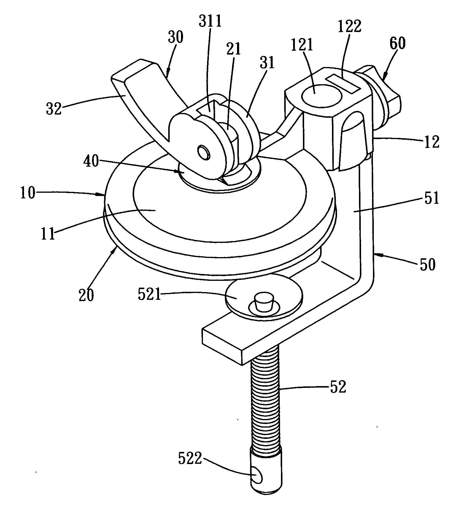
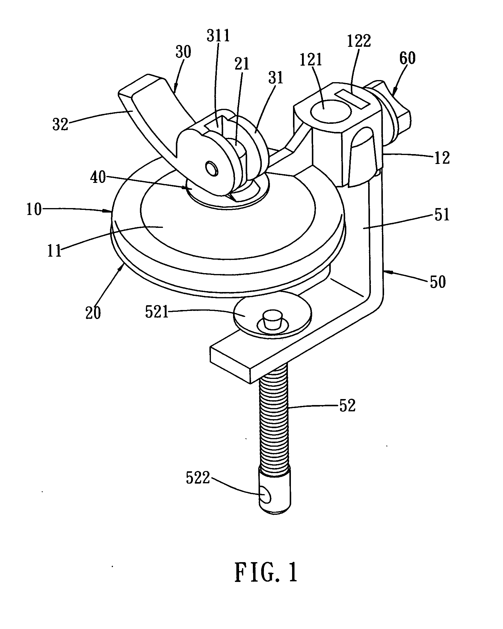
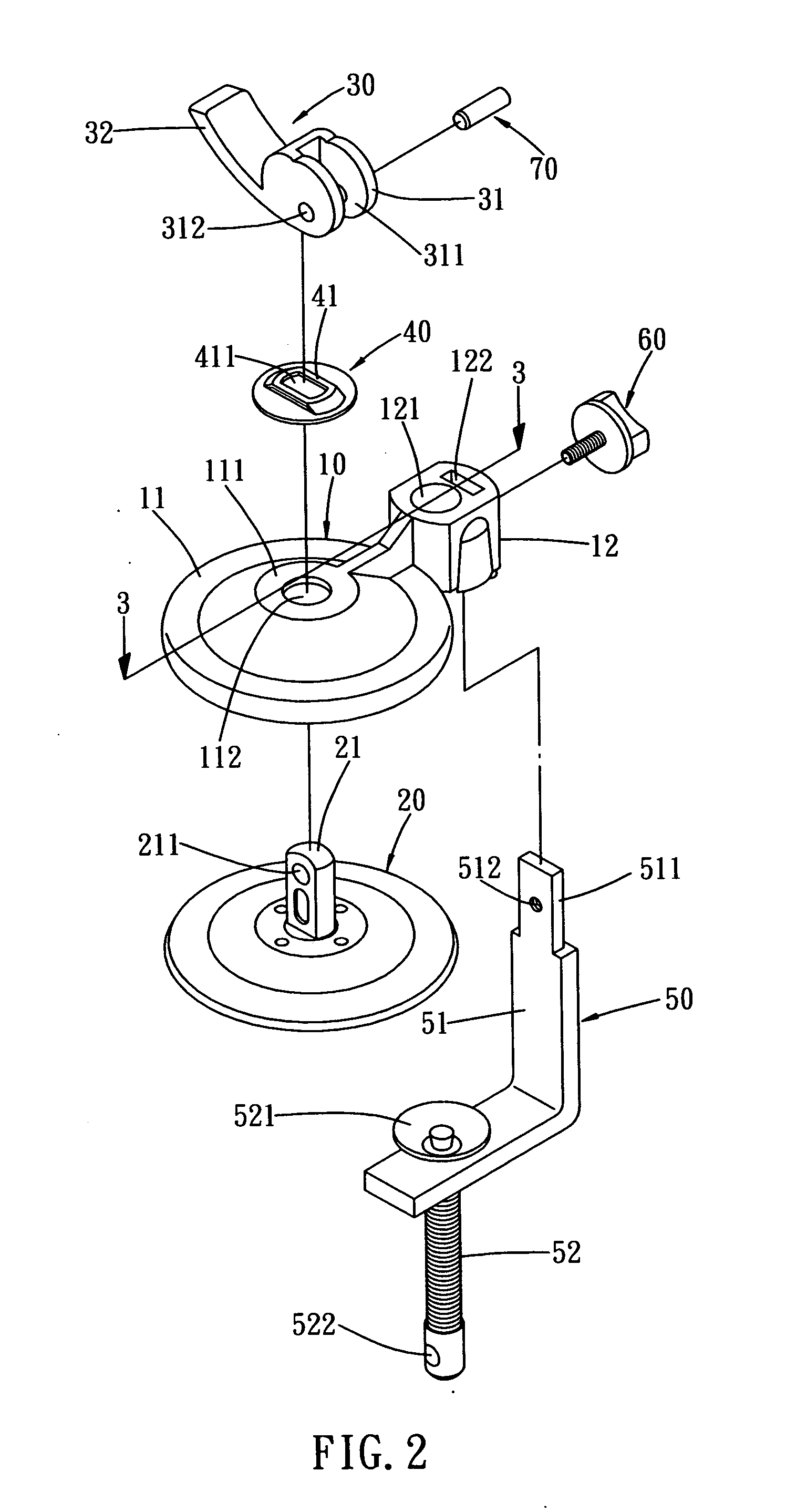
[0029] Referring to the drawings and initially to FIGS. 1-4, a multifunctional holder in accordance with the preferred embodiment of the present invention comprises a base 10, a sucker 20, an actuating handle 30, an elastic plate 40, a clamp 50, and a rotation bolt 60.

[0030] The base 10 includes a disk 11, and a combination seat 12 extended outward from a side of the disk 11. The disk 11 of the base 10 has a top having a center formed with a plane 111 having a center formed with a through hole 112. The combination seat 12 of the base 10 has an inside formed with a circular insertion hole 121 and a rectangular insertion bore 122 communicating with the insertion hole 121, and has a peripheral wall formed with a fixing hole 123 (see FIG. 3) communicating with the insertion bore 122.

[0031] The sucker 20 has a top face having a center provided with an outward extending shaft 21 having a distal end formed with a pivot hole 211. The shaft 21 of the sucker 20 has a substantially rectangul...


PUM


Abstract

A holder includes a base having a disk and a combination seat, an elastic plate mounted on the disk and having a protruding elastic portion, a sucker mounted on a bottom of the disk and having a shaft extended through the through hole of the disk and the slot of the elastic plate, and an actuating handle having an enlarged head pivotally mounted on the shaft and urged on the elastic portion of the elastic plate. Thus, the holder is assembled and disassembled easily and conveniently, thereby facilitating the user mounting the holder. In addition, the holder is assembled rigidly and stably, so that the holder will not become loosened during a long-term utilization, thereby facilitating the user using the holder.

Description

BACKGROUND OF THE INVENTION [0001] 1. Field of the Invention [0002] The present invention relates to a holder, and more particularly to a multifunctional holder that is used to support an article rigidly and stably. [0003] 2. Description of the Related Art [0004] A conventional holder is used for supporting an article, such as a note, a document file, or the like, on a table by the greater weight of the holder. However, the conventional holder cannot support the article rigidly and stably by its own weight, so that the holder easily falls down due to an unintentional touch or hit, thereby causing inconvenience to the user. SUMMARY OF THE INVENTION [0005] The primary objective of the present invention is to provide a holder assembled and disassembled easily and conveniently, thereby facilitating the user mounting the holder. [0006] Another objective of the present invention is to provide a holder that is assembled rigidly and stably, so that the holder will not become loosened during...

Claims


Application Information

Patent Timeline
IPC IPC(8): A45D42/14A47B96/06F04D29/60F16B47/00F16M11/04F16M13/02F21S6/00F21V21/06F21V21/088
CPCF04D29/601F16B47/00F16M11/04F16M13/02F21V21/088F16M2200/027F21S6/00F21V21/06F16M13/022
Inventor HSU, FU-LU
Owner LUH IND CORP
Why Eureka
Try Eureka