

Eyeglass assembly and coupling system
a technology of eyeglasses and couplings, applied in the field of eyeglass assembly, can solve the problems of damage to the lenses, inconvenience but also costs, and not being asthetically pleasing to some customers
- Summary
- Abstract
- Description
- Claims
- Application Information
AI Technical Summary
Benefits of technology
Problems solved by technology
Method used
Image

Examples
Embodiment Construction
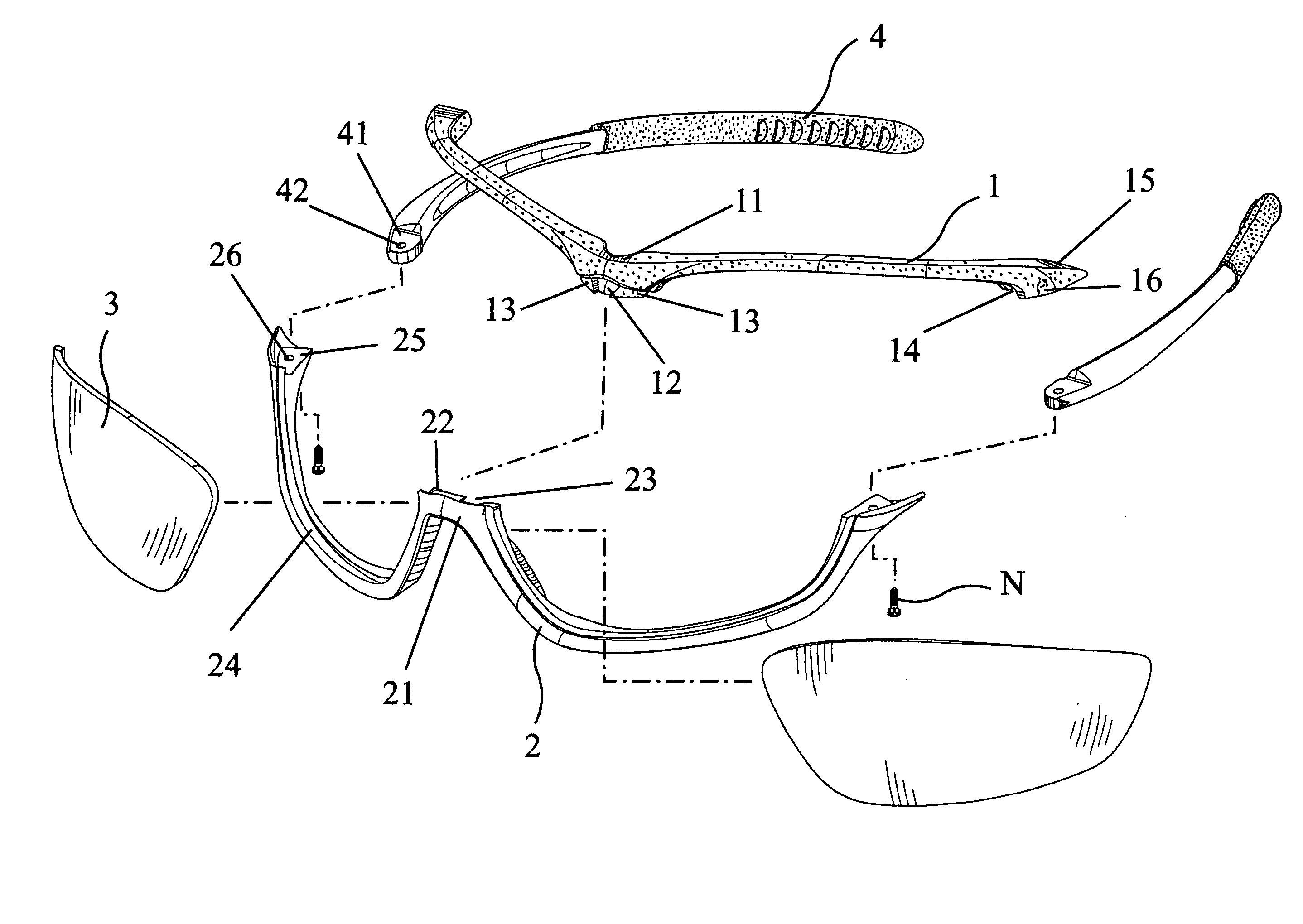
[0026] Referring to FIG. 5, an embodiment of an eyeglass assembly and coupling system in the present invention is assembled by an upper half frame 1, a lower half frame 2, a pair of lenses 3 and a pair of temples 4.
[0027] The upper half frame 1 is provided with an uper hollow 12 in the bridge portion 11, a flanged portion 13 is formed at each side of the upper hollow 12, an elongated groove 14 is provided at one side of each flanged portion 13, and each flat end 15 of the upper half frame 1 is provided with a screw hole 16.
[0028] The lower half frame 2 is provided with a flanged block 22 at the bridge portion 21, a lower hollow 23 is formed at each side of the flanged block 22, an elongated groove 24 is provided at one side of each lower hollow 23, and each flat end 25 of the lower half frame 2 is provided with a screw hole 26.
[0029] The pair of lenses 3 may be colorful or transparent, and their shpaes respectively accord with those of the elongated grooves 14 and 24 of the upper...
PUM
 Abstract
Description
Claims
Application Information