Tilt & lock air handling fixture

Inactive Publication Date: 2005-07-14
PHILIPS LIGHTING NORTH AMERICA CORPORATION
View PDF25 Cites 45 Cited by
  • Summary
  • Abstract
  • Description
  • Claims
  • Application Information

AI Technical Summary

Benefits of technology

[0004] With regard to the foregoing, the present invention eliminates the oversights, difficult

Problems solved by technology

A problem exists because prior art fixtures fail to provide adjustment

Method used


Image

  • Tilt & lock air handling fixture
  • Tilt & lock air handling fixture
  • Tilt & lock air handling fixture

Examples


Embodiment Construction

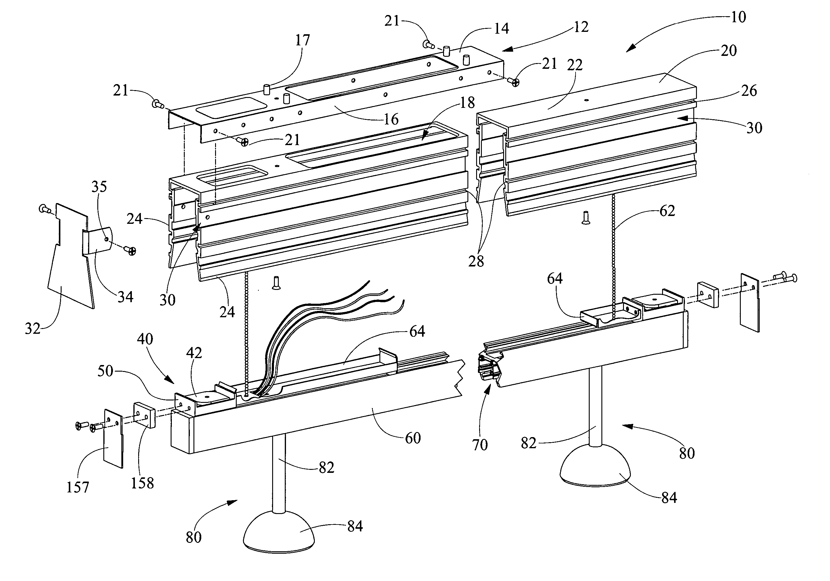
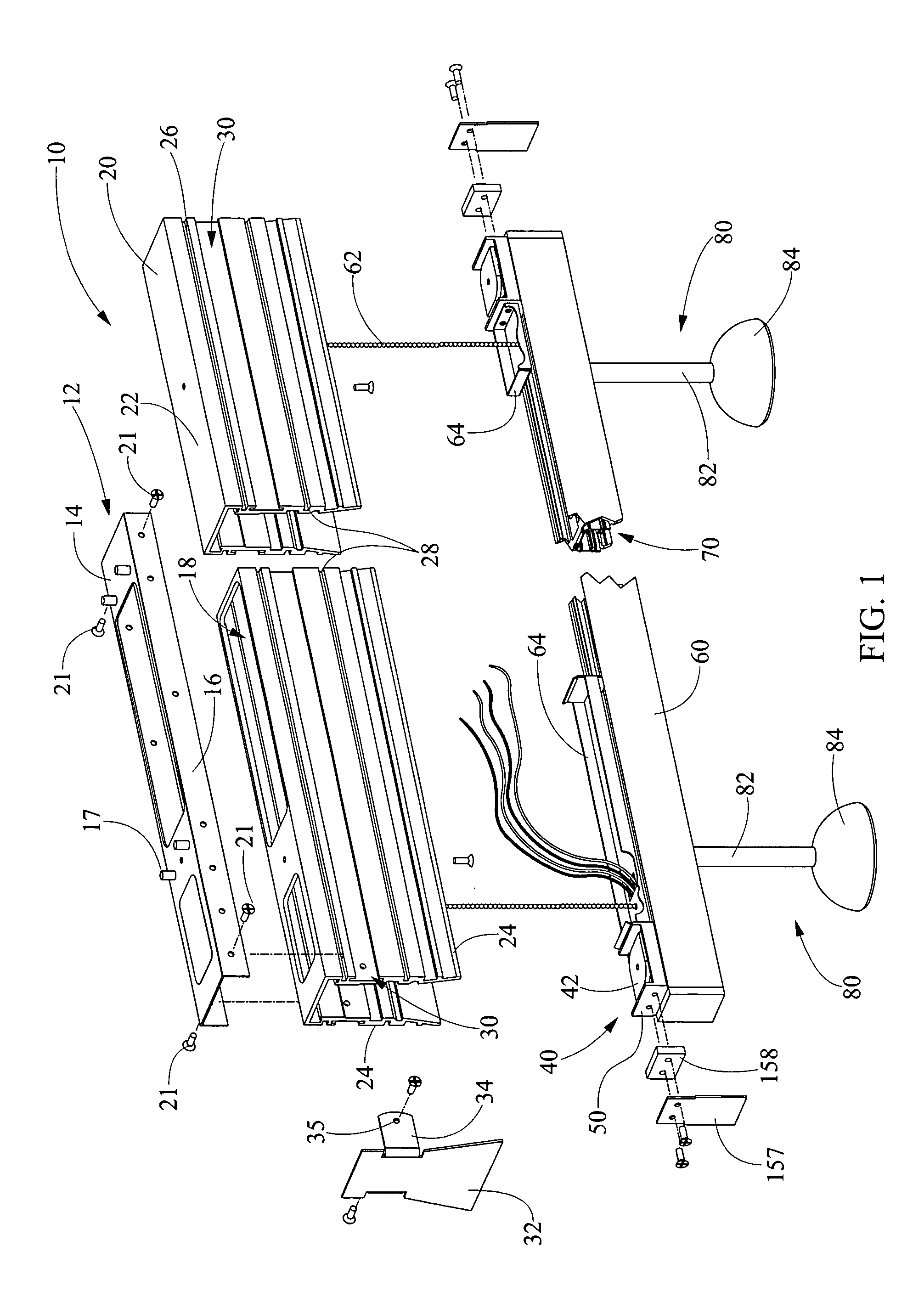
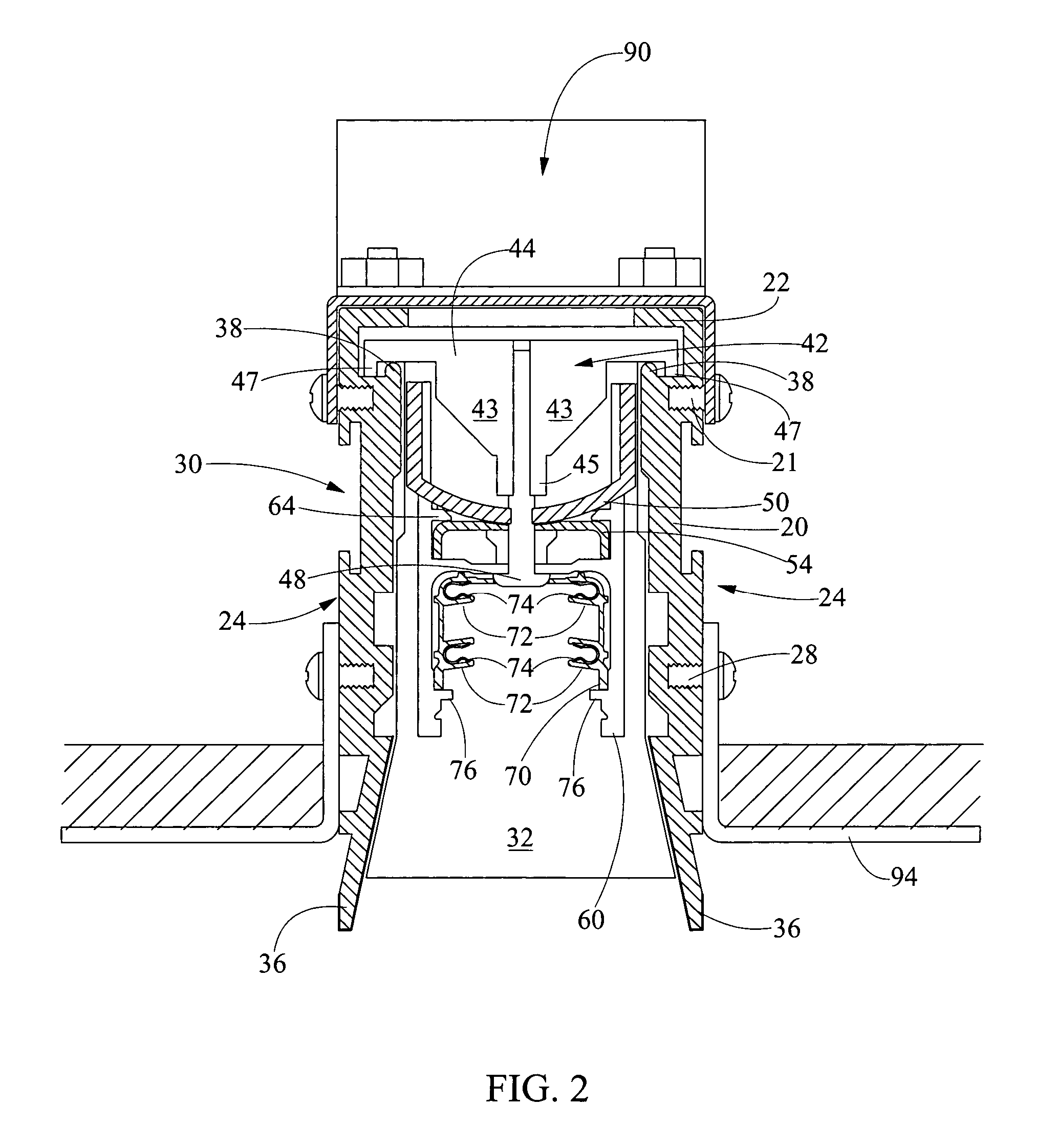
[0022] Referring now in detail to the drawings, wherein like numerals indicate like elements throughout the several views, there are shown in FIGS. 1 through 12 various aspects of a tilt and lock air handling fixture. The tilt and lock air handling fixture may be used with track pendant lighting in sloped ceilings to provide air handling capabilities. In addition, the fixture is adjustable within an air handling channel so that when the pendant lighting depends from the sloped ceiling, the lighting is perpendicular to the floor there below. The present invention provides a light fixture for use with a fluorescent or discharge lamp.

[0023] The present invention provides a fixture which is positioned within a sloped ceiling wherein an air handling plenum is in fluid communication with the fixture. In addition to air handling capability, it is desirable to provide adjustment of the fixture so that a pendant arm depends from a sloped or angled ceiling while being plumb or perpendicular ...


PUM


Abstract

According to the invention, an air handling fixture is provided which can be tilted and locked at a preselected angle when mounted on a sloped ceiling so that a depending pendant tracklight is plumb or perpendicular to a horizontal floor there beneath. The fixture comprises an air handling channel including a plurality of air handling slots, a tilt and lock mechanism, the tilt and lock mechanism having an upper portion, including a toggle lock and casing, and a lower portion, including at least a light retaining component slidably adjustable through a preselected arc.

Description

FIELD OF THE INVENTION [0001] The present invention relates to a light fixture for track and fluorescent lighting. More particularly, the present invention relates to a pendant track lighting fixture for use with a recessed air handling channel allowing for air handling and tilting and locking of the fixture at a preselected angle to compensate for a sloped ceiling. BACKGROUND OF THE INVENTION [0002] When mounting a track type pendant light fixture on a sloped ceiling, the pendant arm depending from the fixture will be positioned at an angle to a horizontal floor there beneath. A problem exists because prior art fixtures fail to provide adjustment so that the pendant arm is perpendicular to a horizontal floor or plumb. [0003] Given the foregoing deficiencies, it will be appreciated that a light fixture is needed which is adjustable to a preselected angle and lockable such that pendant-track type lighting can hang perpendicular to a floor beneath said lighting. SUMMARY OF THE INVENTI...

Claims


Application Information

Patent Timeline
IPC IPC(8): F21S8/06F21V17/18F21V21/02F21V21/30F21V21/34F21V33/00H01R25/14
CPCF21S8/06F21V17/18F21V21/025F21V21/35F21V33/0088H01R25/14F21V21/30
Inventor BERNHART, HORST J.CAMPEAU, RAYMOND A. JR.
Owner PHILIPS LIGHTING NORTH AMERICA CORPORATION
Why Eureka
Try Eureka