
Electrical outlet safety cover

Inactive Publication Date: 2005-07-28
INTERLOCK ELECTRIC
View PDF21 Cites 13 Cited by
  • Summary
  • Abstract
  • Description
  • Claims
  • Application Information

AI Technical Summary

Benefits of technology

[0007] One embodiment of the present invention uses a safety cap including prongs made of a non-electrically conductive material which is attached to a bendable section for rotating the prongs from a position outside an electrical outlet to a position inside an electrical outlet and an adhesive section for connecting the cap to a standard electrical outlet cover plate. The use of the adhesive section allows the cover to be placed on the standard electrical outlet. This embodiment can be made relatively cheaply. Such an embodiment can be a “T”-shaped plastic member with molded-in prongs; a dual unit hinged at a center cross-member; or a cover having an adhesive strip around its frame-like shape. Tabs can be used on the cap to make the cap removal easier. A ridge on the cover back can act as a pivot when the cap is pressed so that the tab may be easily gripped.
[0010] Each receptacle is preferably designed to require two hands to operate so that children will be less likely to accidentally remove the plug.

Problems solved by technology

This exposes him to the danger of shock or even death.
Additionally, an exposed outlet presents the problem of “carbon fires” that can occur when dust accumulates in an outlet.
In spite of generally widespread knowledge of the dangers that electrical outlets present to small children, very few devices are commercially available for denying a child access to an outlet.
A major disadvantage of this type of device is that the disk may easily become lost or mislaid when it is temporarily removed to allow normal use of the outlet.
Such proposals generally provide an inadequate solution either because the safety cover is too easily defeated by a child who is still too young to understand the dangers of electricity or because the covering device is unduly complicated and / or cumbersome.

Method used


Image

  • Electrical outlet safety cover
  • Electrical outlet safety cover
  • Electrical outlet safety cover

Examples


Embodiment Construction

FIGS. 1-4

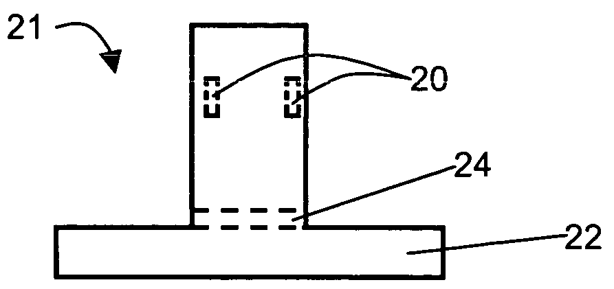
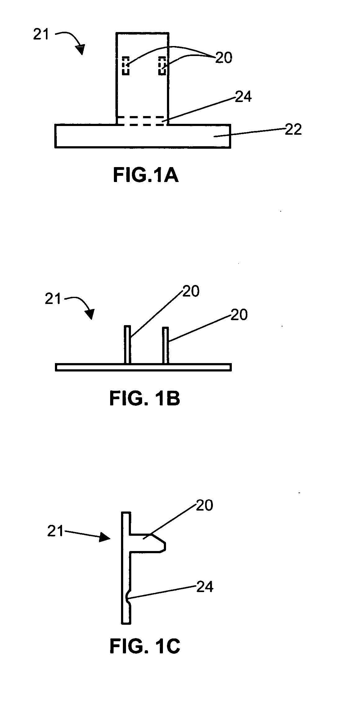
[0032] In the simplest form of the invention (FIGS. 1A-C), a “T”-shaped plastic member 21 has molded-in prongs that articulate into and out of engagement with the outlet slots. The “T”-shaped member has an adhesive strip 22 applied to the back of the horizontal of the “T”, which sticks to the face of a duplex outlet cover plate (not shown). It is thus restrained from loss. A bendable portion 24 allows the prongs 20 to bend in and out of the receptacle (not shown).

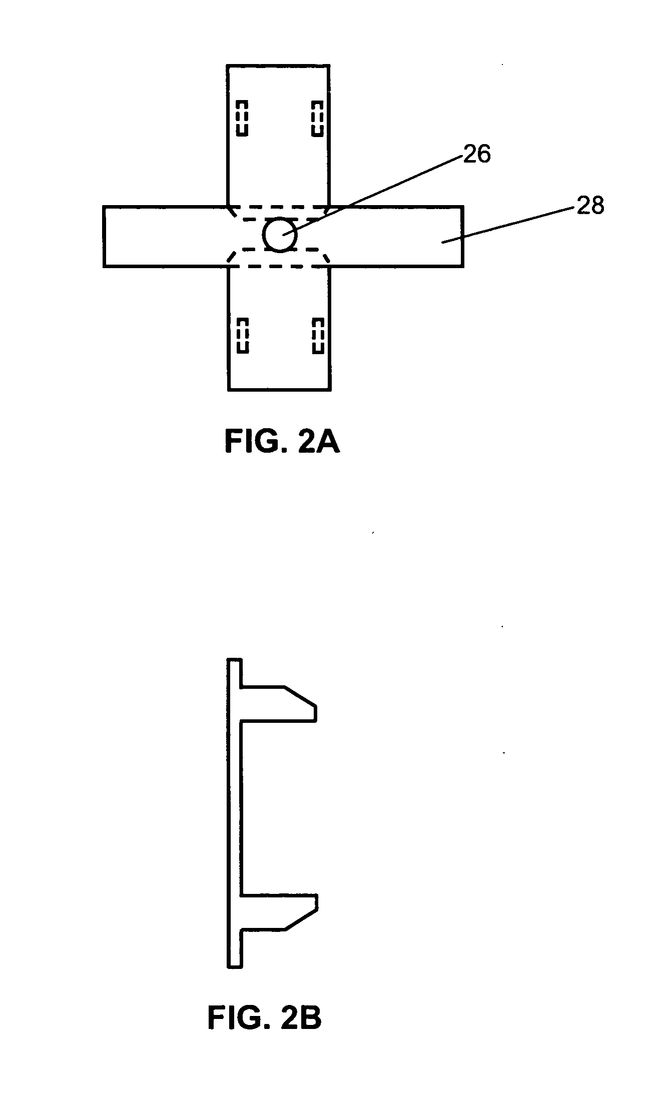
[0033] Another variation (FIGS. 2A-B) has a cross-member in the center having a centrally-disposed hole 26 therein for receiving the mounting screw normally found in duplex outlets. Adhesive at area 28 also helps hold the cover on the outlet.

[0034] Still another variation (FIGS. 3A-B) has an adhesive strip all around its frame-like shape 30 for mounting.

[0035] The embodiment shown in FIG. 4 is similar to the embodiment of FIG. 3. The entire duplex plate is covered except for a square cutout 38 in the center to p...


PUM


Abstract

A safety cap for an electrical outlet having an adhesive section can be attached to a standard outlet cover. Alternately, an outlet cover including two slidable plates including a spring or spring groove can be used to prevent access to the outlet by a child. An elongated member on one plate is used to contact a spring on the other plate. Alternately, the elongated member can fit into a spring groove to bias the plates apart into the closed position. Locking pins can be used to lock the plates onto an aperture at the base of a plug's power prong. Additionally, a recess around each electrical outlet can mate with a respective lip of a plug to provide an interlocking interface between the plug and outlet cover to prevent a child from being able to insert a metal object between the plug and the faceplate.

Description

CROSS-REFERENCE TO RELATED APPLICATIONS [0001] This application is a continuation of co-pending U.S. patent application Ser. No. 09 / 162,387, filed Sep. 28, 1998, which is a divisional of U.S. patent application Ser. No. 08 / 708,344, filed Sep. 6, 1996, now issued as U.S. Pat. No. 5,813,873, which claims the benefit of U.S. Provisional Application Ser. No. 60 / 003,364, filed Sep. 7, 1995.BACKGROUND OF THE INVENTION [0002] In residential and other structures, electrical outlets are generally positioned a short distance above the floor. This makes the outlets readily accessible to small children. A curious child is inclined to test and probe his environment and may stick objects, such as paper clips, into the prong receiving openings of an electrical outlet. This exposes him to the danger of shock or even death. [0003] Additionally, an exposed outlet presents the problem of “carbon fires” that can occur when dust accumulates in an outlet. [0004] In spite of generally widespread knowledge...

Claims


Application Information

Patent Timeline
IPC IPC(8): H01R13/443H01R31/06
CPCH01R13/443H01R13/447H02G3/14H01R31/06H01R13/453
Inventor MCBAIN, THEODORE
Owner INTERLOCK ELECTRIC
Features
  • Generate Ideas
  • Intellectual Property
  • Life Sciences
  • Materials
  • Tech Scout
  • Unparalleled Data Quality
  • Higher Quality Content
  • 60% Fewer Hallucinations
Learn More