Brake pad backing plate and method of making the same

a technology of brake pads and backing plates, which is applied in the direction of friction linings, mechanical equipment, brake members, etc., can solve the problems of unnecessarily difficult and expensive forming discontinuities on the backing plates, and achieve cost savings

Inactive Publication Date: 2005-07-28
HAYEK DR SALIM
View PDF31 Cites 29 Cited by
  • Summary
  • Abstract
  • Description
  • Claims
  • Application Information

AI Technical Summary

Benefits of technology

[0006] A method in accordance with a present invention involves cutting a brake pad backing plate out of a sheet having a plurality of discontinuities formed therein. A brake pad may be manufactured by subsequently securing a friction pad to the brake pad backing plate. There are a number of cost saving advantages associated with such a method. For...

Problems solved by technology

For example, the present inventor has determined that the conventional method of forming discontinuities on the backing plate, i.e. forming the discont...

Method used


Image

  • Brake pad backing plate and method of making the same
  • Brake pad backing plate and method of making the same
  • Brake pad backing plate and method of making the same

Examples


Embodiment Construction

[0027] The following is a detailed description of the best presently known modes of carrying out the inventions. This description is not to be taken in a limiting sense, but is made merely for the purpose of illustrating the general principles of the inventions.

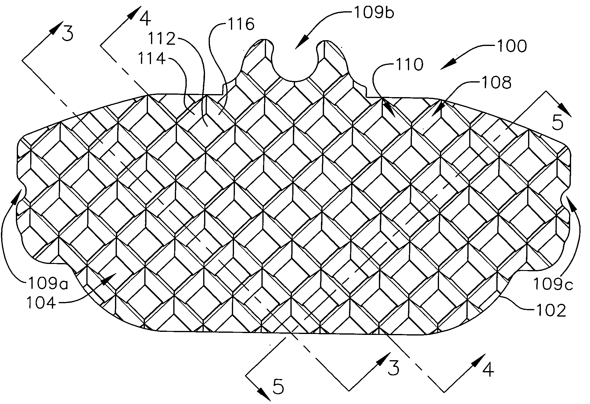
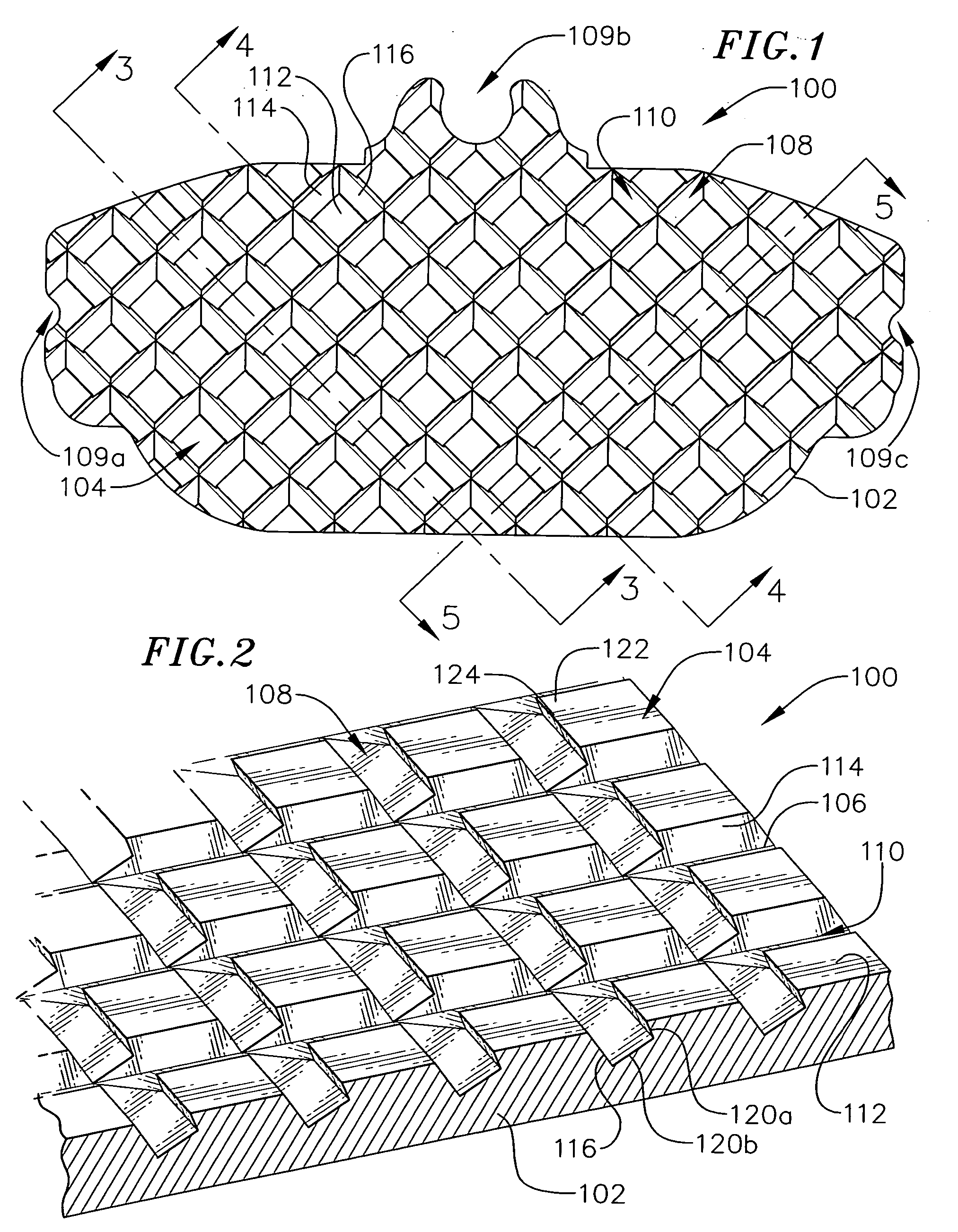
[0028] As illustrated for example in FIGS. 1 and 2, a brake pad backing plate 100 in accordance with one embodiment of a present invention includes a plate member 102 and a plurality of protrusions 104 extending outwardly from the front side 106 of the backing plate. The protrusions 104 add to the overall bonding surface area of the backing plate 100. The rear side 107 of the backing plate is generally planar, as is the front side 106. The protrusions 104 are separated by a first set of parallel channels 108 (which extend down and to the left in FIG. 1) and a second set of parallel channels 110 (which extend down and to the right in FIG. 1). Although the present inventions are not limited to any particular configuration, the...


PUM


Abstract

Brake pads, brake pad backing plates and methods of producing the same.

Description

BACKGROUND OF THE INVENTIONS [0001] 1. Field of Inventions [0002] The present inventions relate generally to brake pads and brake pad backing plates. [0003] 2. Description of the Related Art [0004] Brakes, which are used to control the speed of a wide variety of vehicles, commonly include a brake pad that engages a rotor. The brake pads consist of friction pad and a backing plate that is used to mount the brake pad on the brake. The backing plate / friction pad connection must be very secure because of the high levels of shear and tensile forces that are applied to the friction pad by the rotor, vehicle vibrations, etc. Some conventional methods of securing the friction pad to the backing plate involve molding the friction pad onto the backing plate. Frequently, discontinuities are formed on the surface of the backing plate in order to increase the surface area of the backing plate / friction pad bond and to create mechanical interference between the two. [0005] The present inventor has...

Claims


Application Information

Patent Timeline
IPC IPC(8): F16D65/04F16D69/04
CPCF16D69/04F16D2069/0491F16D2069/0483F16D2069/0441
Inventor UWAYDAH, MUNIR
Owner HAYEK DR SALIM
Why Eureka
Try Eureka