Bone fixation element

a bone fixation element and bone technology, applied in the field can solve the problems of increasing stiffness and reducing stiffness, and achieve the effects of promoting new bone growth, improving long-term anchorage in bone, and varied stiffness of bone fixation elements

Inactive Publication Date: 2005-07-28
DEPUY SYNTHES PROD INC
View PDF7 Cites 173 Cited by
  • Summary
  • Abstract
  • Description
  • Claims
  • Application Information

AI Technical Summary

Benefits of technology

This patent describes an improved way for fixing bones that allows for flexibility in how strong it needs to be. This makes sure that the bone stays secure over longer periods of time, particularly if there are any issues with bone quality like osteoporosis. It also helps improve the surrounding areas where the bone is being fixed by promoting bone growth and keeping other important parts of the body's structure intact.

Problems solved by technology

Implants currently available often cause damage to the surrounding tissue including bone when they are inserted due to their rigidity. This results in reduced strength of the bone and increased risk of complications like pain and inflammation. One solution proposed involves designing implants with holes or channels to allow for growth of new bone cells and improved attachment to the patient's own bone. Another approach includes reducing the size of the implant while maintaining its stability. These solutions address some but not all aspects of the problem.

Method used


Image

  • Bone fixation element
  • Bone fixation element
  • Bone fixation element

Examples


Embodiment Construction

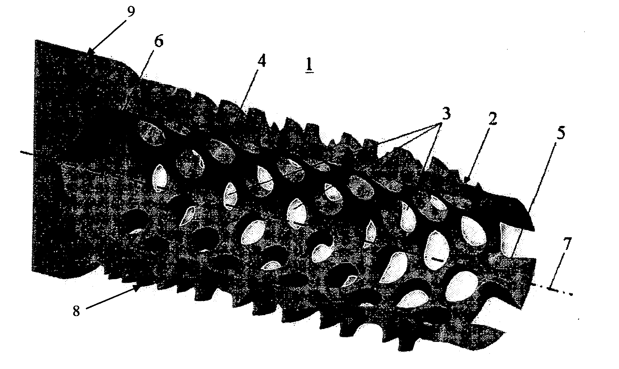
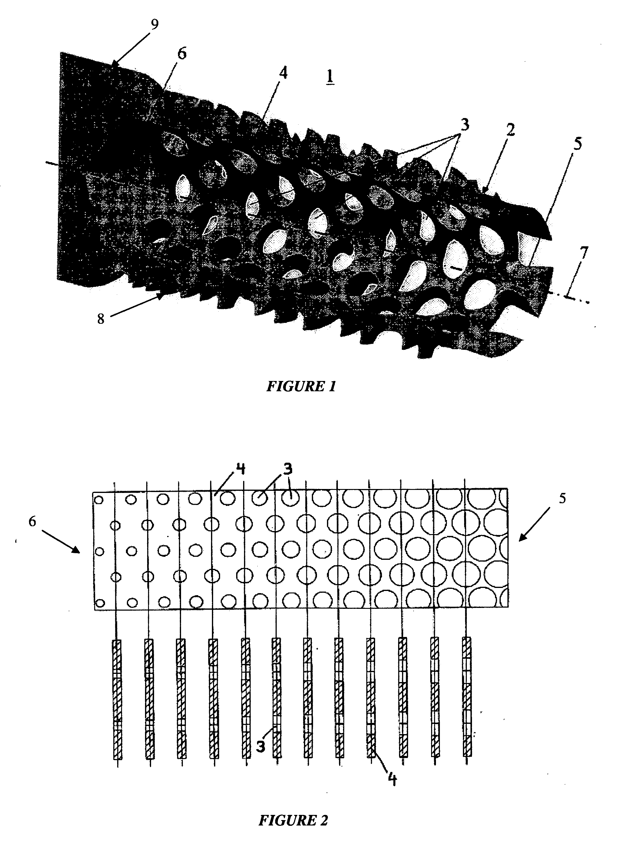
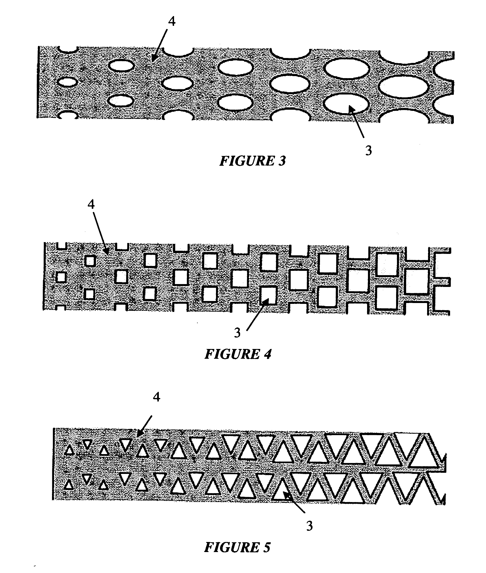
[0018] As shown in FIG. 1, the bone fixation element 1 may be in the form of a hollow member 2 having a wall 4, a plurality of perforations 3 in the wall 4, a front end 5 suitable for introduction into bone, a rear end 6 and a longitudinal axis 7. Preferably, the hollow member 2 may be in the form of a cylinder with an opened front end 5. Moreover, the wall 4 may be a circumferential surface. It should, however, be understood that those of ordinary skill in the art will recognize many modifications and substitutions which may be made to various elements of the present invention.

[0019] As shown, at least a portion of the wall 4 may be provided with an external thread 8 for engaging bone or tissue. The thread 8 may be on a portion adjacent the rear end 6. Additionally, the rear end 6 of the bone fixation element 1 may be provided with means, for example, an enlarged portion or conical head 9, which may be inserted in / attached to a bone plate (not shown).

[0020] Some of the advantages...


PUM


Abstract

A bone fixation element consisting of a hollow member having a wall, a plurality of perforations locating in the wall, a front end which is suited for insertion into the bone, a rear end, and a longitudinal axis. The stiffness of the hollow member may vary along its longitudinal axis from the rear end to the front end. Changes in the porosity and/or the thickness of the wall of the bone fixation element may result in changes in stiffness of the bone fixation element. An increase in porosity and/or decrease in thickness may result in a decrease in stiffness, and a decrease in porosity and/or increase in thickness may result in an increase in stiffness.

Description


Claims


Application Information

Patent Timeline
Owner DEPUY SYNTHES PROD INC
Why Eureka
Try Eureka