Processes for additively manufacturing orthopedic implants followed by eroding

a technology of additive manufacturing and orthopedic implants, applied in additive manufacturing, manufacturing tools, prosthesis, etc., can solve the problems of external surfaces that may be mechanically eroded, internal surfaces that may be mechanically eroded, external surfaces that may be chemically eroded, etc., to facilitate new bone growth and eliminate internal pores of metal

Active Publication Date: 2022-06-28
TITAN SPINE
View PDF252 Cites 2 Cited by
  • Summary
  • Abstract
  • Description
  • Claims
  • Application Information

AI Technical Summary

Benefits of technology

[0011]The heating and / or stress-relieving steps may be carried out under a vacuum. The heating and / or stress-relieving steps may be carried out under atmospheric pressure and in an inert environment. In some aspects, the compressing substantially eliminates internal pores of the metal.
[0012]The mechanical eroding may comprise eroding the one or more surfaces with an organic or inorganic medium. The organic or inorganic media used for eroding are preferably dissolvable in an aqueous medium, including an acidic aqueous medium or an alkaline aqueous medium. The mechanical erosion preferably imparts micro-scale structures into the one or more surfaces. The micro-scale structures may comprise a maximum peak-to-valley height of from about 1 μm to about 200 μm, a skewness of from about −2 to about 2, and a kurtosis of from about 1 to about 9. In some aspects, mechanical eroding removes particulate debris from the one or more surfaces. The debris may comprise partially or fully unmelted or unsintered powder, particles, granules, wires, fragments, or combinations thereof of the metal. External surfaces may be mechanically eroded. Internal surfaces may be mechanically eroded. The eroded surfaces may contact bone or a bone graft material upon implantation of the implant within the body. The eroded surfaces may facilitate new bone growth such that the surfaces do not contact bone or a bone graft material immediately upon and following implantation, but contact bone a period of time following implantation when new bone grows on and out from such surfaces.

Problems solved by technology

External surfaces may be mechanically eroded.
Internal surfaces may be mechanically eroded.
External surfaces may be chemically eroded.
Internal surfaces may be chemically eroded.

Method used


Image

  • Processes for additively manufacturing orthopedic implants followed by eroding
  • Processes for additively manufacturing orthopedic implants followed by eroding
  • Processes for additively manufacturing orthopedic implants followed by eroding

Examples


example 1

Implant Surfaces Additive and Subtractive Manufacture Process

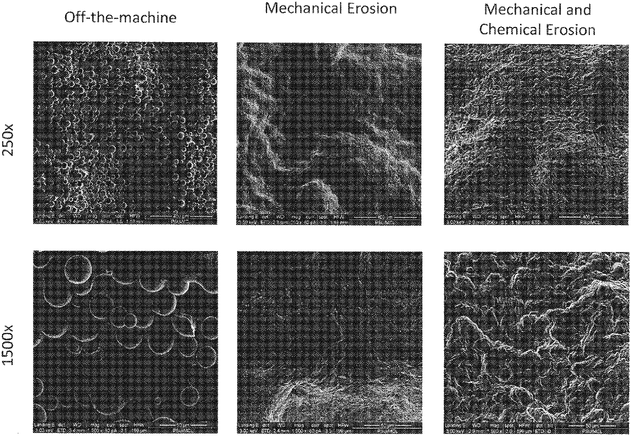
[0083]A number of test discs of a titanium alloy including 6% aluminum and 4% vanadium were fabricated using either laser sintering or electron beam melting (EBM) by either layering from the bottom surface to the top surface (horizontal) or by layering from the anterior surface to the posterior surface (vertical). For each layer, the titanium alloy particles were deposited, first onto a platform surface of the additive manufacturing device, and then successively onto melt-assembly of each layer. The particles were melted together by laser sintering or EBM. Accordingly, the top surface of a test disc fabricated in a horizontal build direction is parallel to the deposited layers, and the top surface of a test disc fabricated in a vertical build direction is perpendicular to the deposited layers.

[0084]Following additive fabrication, the unrefined test discs were divided into two groups. The first group was further subject to ...


PUM

PropertyMeasurementUnit
peak-to-valley heightaaaaaaaaaa
heightaaaaaaaaaa
maximum peak-to-valley heightaaaaaaaaaa

Abstract

Orthopedic implants produced by additive manufacture, followed by refinement of exterior and interior surfaces trough mechanical erosion, chemical erosion, or a combination of mechanical and chemical erosion. Surface refinement removes debris, and also produces bone-growth enhancing micro-scale and nano-scale structures.

Description

CROSS REFERENCE TO RELATED APPLICATIONS[0001]This application claims priority to International Patent Application PCT / US2016 / 062999 filed on Nov. 21, 2016, which claims priority to U.S. Provisional Application No. 62 / 258,239, filed on Nov. 20, 2015, the contents of which are incorporated by reference herein, in their entirety and for all purposes.FIELD OF THE INVENTION[0002]The invention relates generally to the field of medical implant manufacture. In particular, the invention relates to a production process in which medical implants are prepared by an additive process, followed by eroding of external surfaces and, in some aspects, also eroding of internal surfaces.BACKGROUND OF THE INVENTION[0003]Various publications, including patents, published applications, technical articles and scholarly articles are cited throughout the specification. Each of these cited publications is incorporated by reference herein, in its entirety and for all purposes.[0004]Orthopedic implants can be ma...

Claims


Application Information

Patent Timeline
Patent Type & Authority Patents(United States)
IPC IPC(8): B22F3/24C22C1/04B33Y10/00B33Y40/00A61L27/04B24C3/32B22F10/00B24C11/00B24C1/00A61L27/06B22F5/10B22F10/20
CPCB22F3/24A61L27/04A61L27/06B22F5/10B22F10/20B24C3/32B24C3/325B24C11/00B33Y10/00B33Y40/00C22C1/0458A61L2400/12A61L2430/02B22F2003/241B22F2003/244B22F2003/247B22F2301/205B22F2998/10B24C1/00Y02P10/25B22F10/60B22F10/32B22F10/28B22F10/25B33Y40/20B22F3/15B23H3/00
Inventor GALLAGHER, MICHELLE B.SCHNEIDERBERG, MARK E.
Owner TITAN SPINE
Why Eureka
Try Eureka