Non-resiliency body-contact protective helmet interface structure

Inactive Publication Date: 2005-08-04
MJD INNOVATIONS
View PDF64 Cites 48 Cited by
  • Summary
  • Abstract
  • Description
  • Claims
  • Application Information

AI Technical Summary

Benefits of technology

[0010] The association which exists between the load-cushioning structure and a helmet shell (rigid), is that the helmet shell converts whatever kind of specific impact occurs to it from the outside to a broad-area, blunt-trauma kind of event which is delivered directly to the load-cushioning structure without there being any interposed, other lo

Problems solved by technology

Airspace between the webbing and the shell of the helmet contributes somewhat to the ballistic, and significantly to the cooling, capabilities of the helmet, but such a webbing system has proven consistently (a) to do a poor job of cushioning shock loads delivered to the wearer's head through the subject helmet, and (b) to be quite uncomfortable, and thus to be the source of many complaints from users.
This behavior, in the “world” of a hel

Method used


Image

  • Non-resiliency body-contact protective helmet interface structure
  • Non-resiliency body-contact protective helmet interface structure

Examples


Embodiment Construction

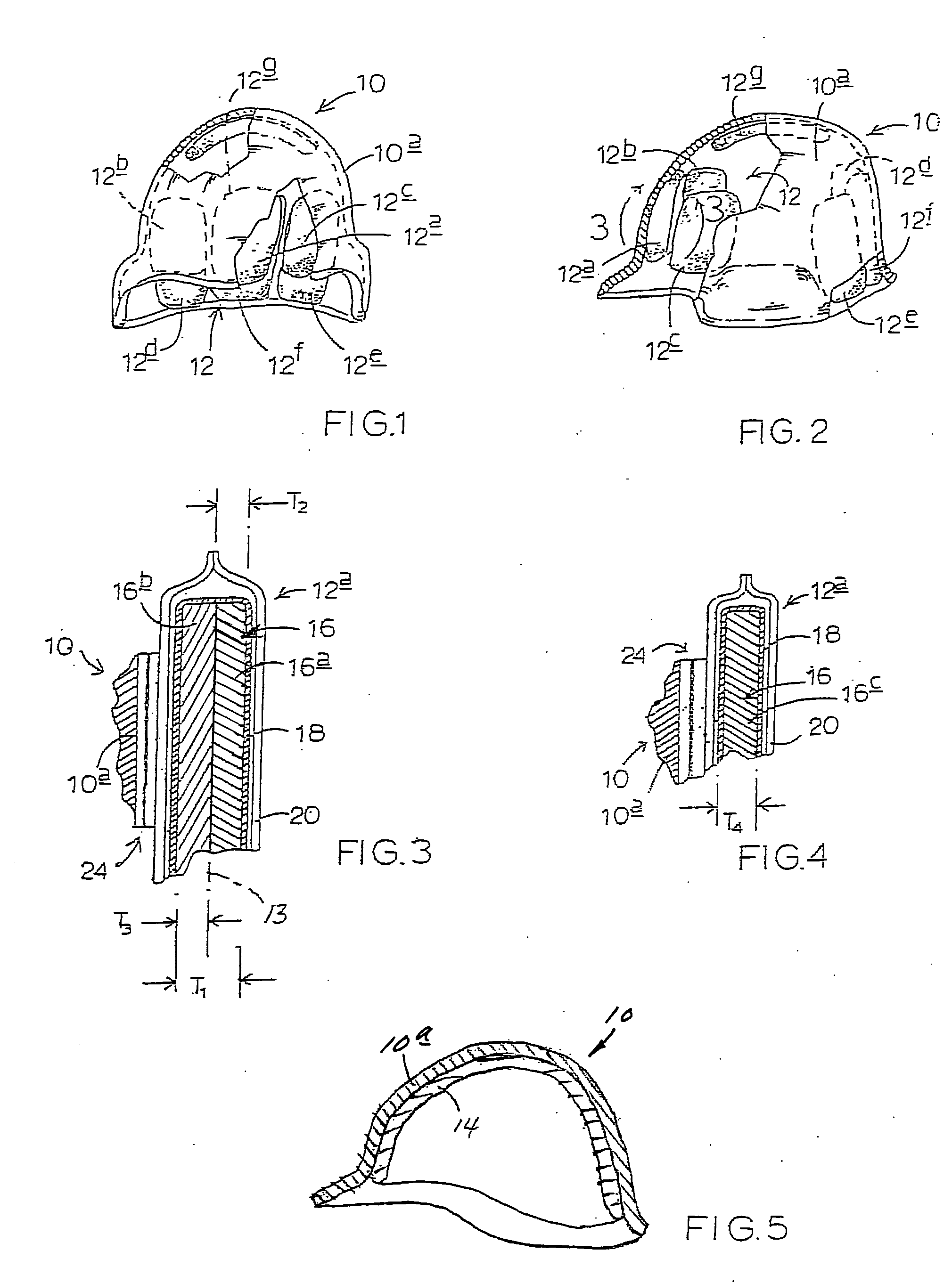
[0020] Turning attention now to FIGS. 1, 2 and 3, indicated generally at 10 (FIGS. 1 and 2) is a military helmet including a shell 10a. In all respects, shell 10a is completely conventional in construction, and might have any one of a number of different specific constructions and configurations.

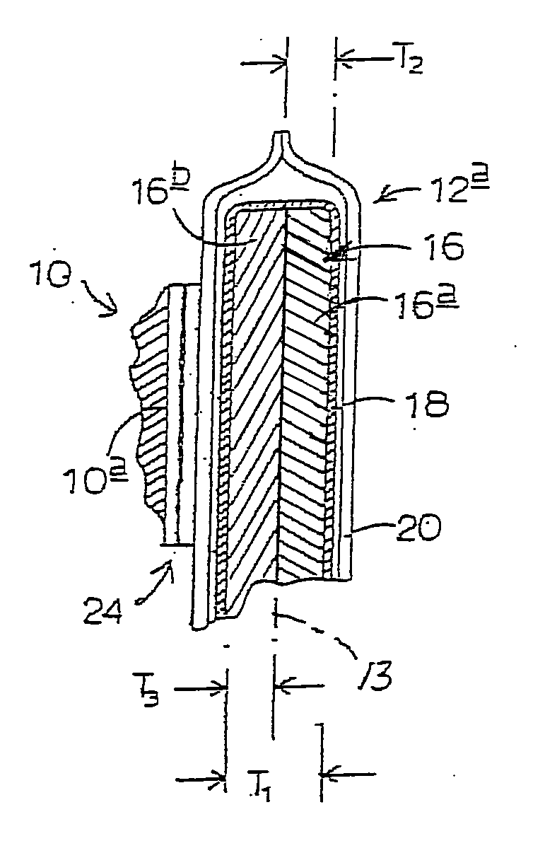
[0021] Fastened in one of a variety of appropriate manners on the inside, concave, dome-like surface of shell 10a is an installation 12 of shock-absorbing, load-cushioning interface structure constructed in accordance with the present invention. Installation 12, in the particular setting illustrated in these figures and now being described, includes seven, individual, multi-layer, load-cushioning, interface-structure pads 12a, 12b, 12c 12d, 12e, 12f, 12g, each of which includes one preferred form of a central, or core, load-cushioning instrumentality possessing certain characteristics which are key to the structure and functionality of the present invention. Pad 12a is joined to the inside ...


PUM

PropertyMeasurementUnit
Resilienceaaaaaaaaaa

Abstract

Shock-absorbing, load-cushioning interface structure for use inside, and in operative cooperation with, the shell of a helmet for operative interposition such a shell and the head of a wearer. This structure is characterized with features and performances including (a) compression-deformation-and-slow-return viscoelasticity, (b) non-springy (anti-rebound) during a return from deformation, (c) acceleration-rate(strain-rate)-sensitivity, and (d) a durometer associated with an ILD number which is no less than about 15-ILD.

Description

CROSS REFERENCES TO RELATED APPLICATIONS [0001] This application is a continuation-in-part from currently co-pending U.S. patent application Ser. No. 10 / 156,074, filed May 27, 2002 for “Body-Contact Protective Interface Structure and Method”, which application is a continuation from U.S. patent application Ser. No. 09 / 942,987, filed Aug. 29, 2001, entitled “Body-Contact Cushioning Interface Structure and Method”, which is a continuation from U.S. patent application Ser. No. 09 / 390,518, filed Sep. 3, 1999, entitled “Body-Contact Cushioning Interface Structure”, which application claims priority to U.S. Provisional Application Ser. No. 60 / 099,208, filed Sep. 3, 1998, entitled “Body Contact System and Structure for Wearable Garments, such as a Helmet.” The disclosure contents of each of these prior-filed patent applications are hereby incorporated herein by reference.BACKGROUND AND SUMMARY OF THE INVENTION [0002] The present invention relates to a human-body protective, cushioning helm...

Claims


Application Information

Patent Timeline
IPC IPC(8): A42B3/12B32B3/26B32B25/08B32B33/00
CPCA42B3/121A42B3/127B32B3/26F16F2236/045B32B33/00F16F9/30B32B25/08B32B2571/00B32B2307/7265B32B3/04B32B2307/724B32B25/04
Inventor DENNIS, MICHAEL R.
Owner MJD INNOVATIONS
Why Eureka
Try Eureka