Variable rate control pedal

a variable rate, control pedal technology, applied in the direction of mechanical control devices, controlling members, limiting/preventing/returning movement of parts, etc., can solve the problems of introducing additional friction and/or slack in the control of the system, requiring many components, and difficult of impossible to design such systems to achieve some desired stroke ratio profiles

Inactive Publication Date: 2005-08-04
INTIER AUTOMATIVE CLOSURES INC
View PDF23 Cites 7 Cited by
  • Summary
  • Abstract
  • Description
  • Claims
  • Application Information

AI Technical Summary

Benefits of technology

[0006] It is an object of the present invention to provide a novel control pedal assembly which can provide a variable stroke ratio between the pedal and the control device and which obviates or mitigates at least one disadvantage of the prior art.

Problems solved by technology

Such approaches suffer from disadvantages in that they require extra linkage parts, introducing additional friction and / or slack in the control of the system.
Further, it can be difficult of impossible to design such systems to achieve some desired stroke ratio profiles.
These systems also suffer from disadvantages in that they only operate for cable-driven control mechanisms and that they require many components.
Further, such systems are quite limited in how the stroke ratio can be changed over the stroke of the pedal and, for example, it can be very difficult, if not impossible, to change from an increasing ratio to a decreasing ratio over the pedal stroke.

Method used


Image

  • Variable rate control pedal
  • Variable rate control pedal
  • Variable rate control pedal

Examples


Embodiment Construction

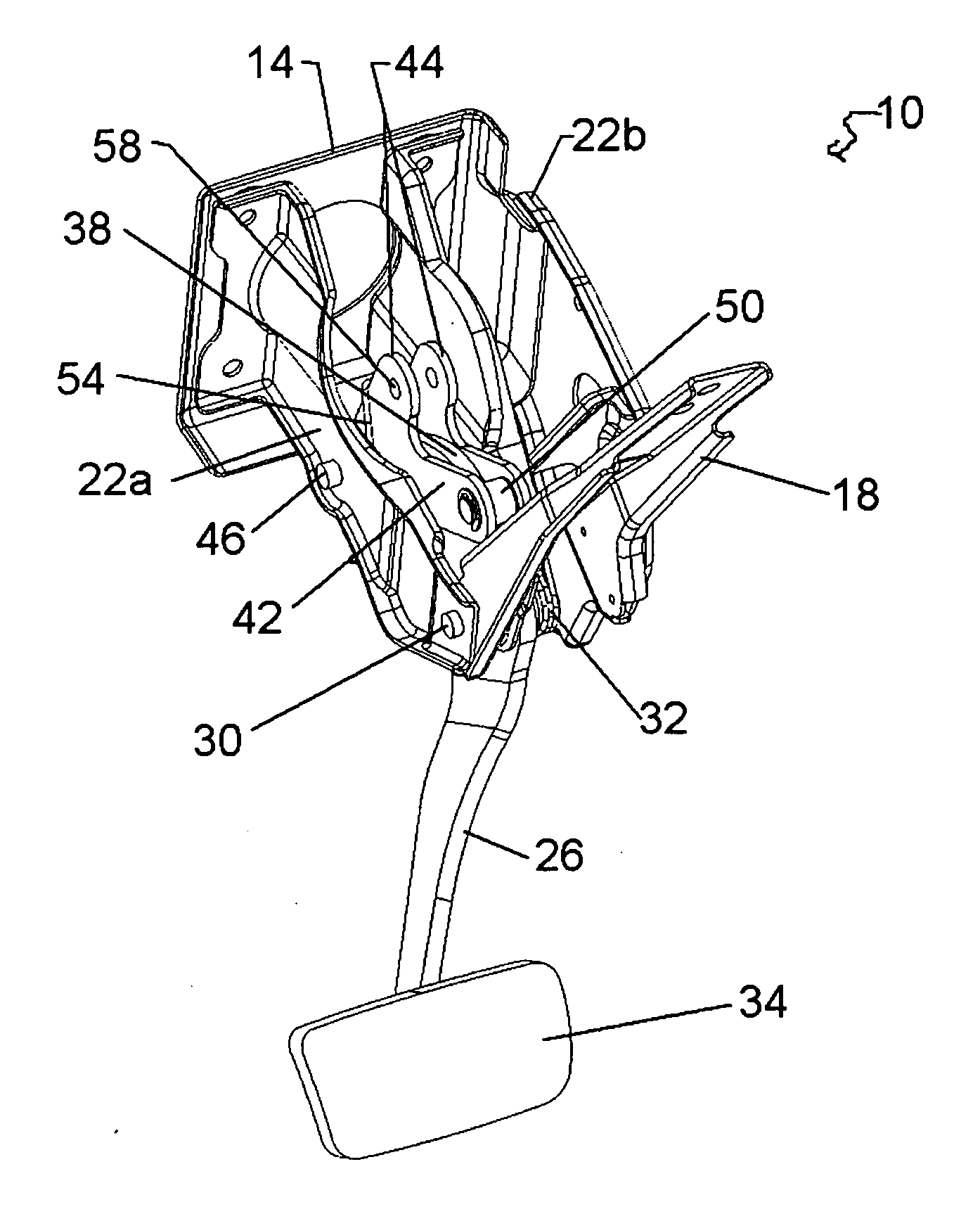
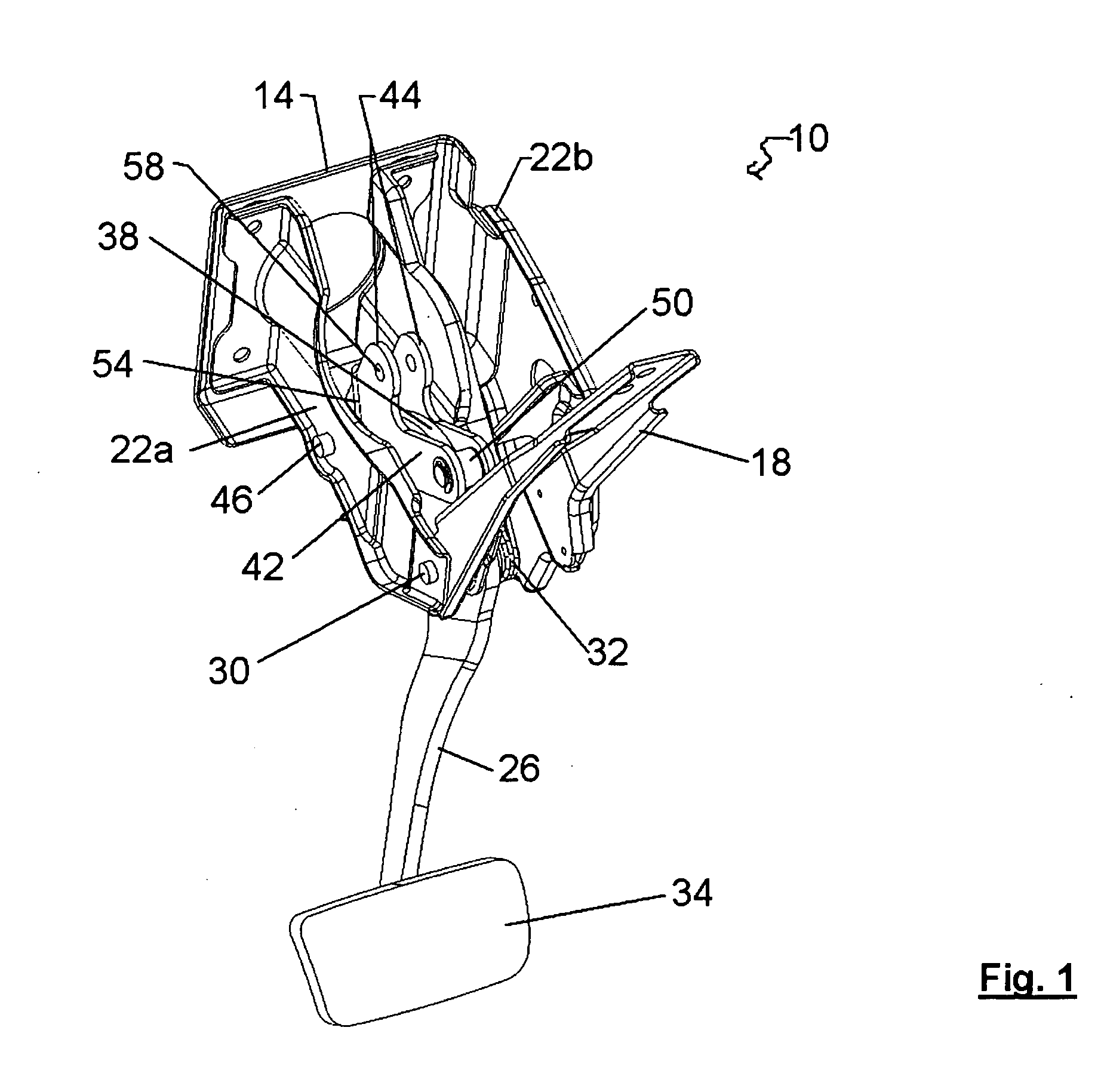
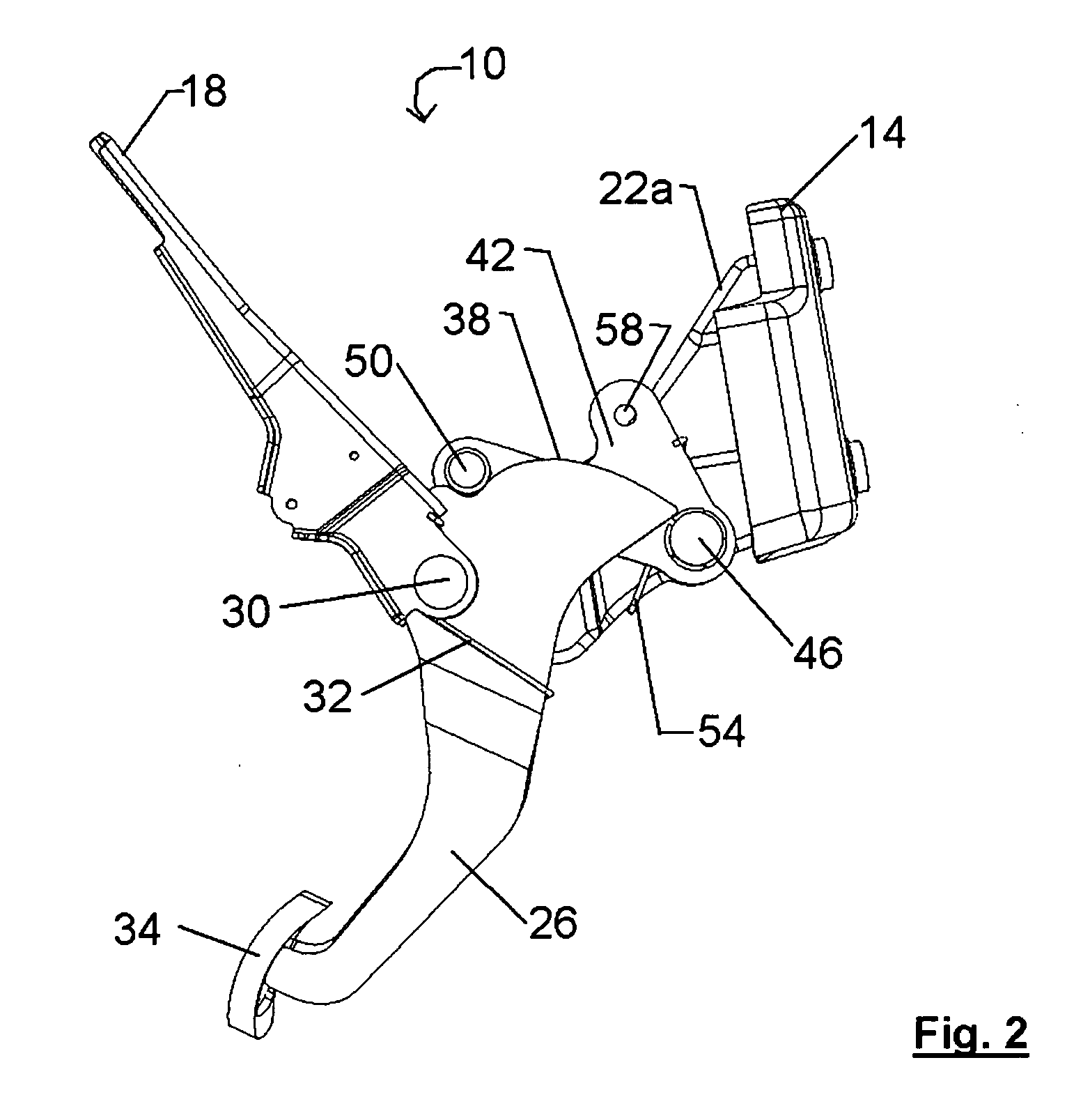
[0014] A control pedal assembly in accordance with the present invention is indicated generally at 10 in FIGS. 1 and 2. Assembly 10 includes a mounting frame 14 and a support 18 to attach assembly 10 to a vehicle.

[0015] A pair of side frames 22a, 22b extend between mounting frame 14 and support 18 and a pedal arm 26 is connected to assembly 10 by a pivot pin 30 extending between side frames 22a, 22b. A torsion spring 32 acts between pedal arm 26 and support 18 to bias pedal arm 26 to the at rest position illustrated in FIGS. 1 and 2.

[0016] Pedal arm 26 includes a lower portion wherein a foot pedal 34 is mounted and an upper portion which includes an actuator surface 38. As illustrated, actuator surface 38 has the form of an eccentric, or changing radius, curve.

[0017] A two-lobed control member 42, comprising a pair of spaced plates 44, is also mounted between side frames 22a, 22b and about actuator surface 38 by a pivot pin 46. One lobe of member 42 includes a roller 50 which is ...


PUM


Abstract

A control pedal assembly includes an eccentric curve as an actuator surface at one end of a pedal arm and a control member includes a first lobe with a roller that rides on the actuator surface and a second lobe that receives a connector rod to a control device to be controlled by the pedal. The eccentric curve changes the stroke ration between the pedal stroke and the connector rod stroke as the pedal is depressed. Designers can simply and efficiently vary the stroke ratio as desired by selecting an appropriate curve for the actuator surface.

Description

FIELD OF THE INVENTION [0001] The present invention relates to control pedals for vehicles. More specifically, the present invention relates to a control pedal assembly which provides a variable ratio between the pedal stroke and the stroke of the control device operated by the pedal. BACKGROUND OF THE INVENTION [0002] Control pedals are employed in vehicles to actuate control devices for a variety of systems including brakes, clutches and accelerators. The control devices can be cables, hydraulic master cylinders or others. [0003] In many circumstances, it is desired and / or required that the ratio between the stroke of the control pedal and the stroke of the control device, the “stroke ratio”, not be constant over the stroke of the pedal. For example, in braking systems it can be desired that for an initial portion of the stroke of the control pedal, the control device be stroked a correspondingly high amount to quickly bring the brake shoes, and / or pads, into engagement with the d...

Claims


Application Information

Patent Timeline
Patent Type & Authority Applications(United States)
IPC IPC(8): B60K23/02B60T7/04G05G1/30G05G1/44G05G5/03G05G7/04
CPCG05G1/30Y10T74/20528G05G5/03G05G1/44
Inventor DJORDJEVIC, NEBOJSA
Owner INTIER AUTOMATIVE CLOSURES INC
Why Eureka
Try Eureka