Piezoelectric actuator and head assembly using the piezoelectric actuator

a piezoelectric actuator and actuator technology, applied in the direction of maintaining head carrier alignment, generator/motor, instruments, etc., can solve the problems of deteriorating positioning accuracy, affecting production process, and affecting the quality of the produ

Inactive Publication Date: 2005-08-04
FUJITSU LTD
View PDF7 Cites 4 Cited by
  • Summary
  • Abstract
  • Description
  • Claims
  • Application Information

AI Technical Summary

Benefits of technology

[0013] Therefore, it is an object of the present invention to provide a head assembly having a wiring structure by which an electrode leading out portion does not disturb deformation of a piezoelectric actuator upon application of a voltage.
[0014] It is another object of the present invention to provide a piezoelectric actuator which can eliminate sag of an electrode upon cutting of individual piezoelectric actuators and enhance the electric reliability and a method of producing the piezoelectric actuator.

Problems solved by technology

Therefore, it is a technical problem how to achieve accurate positioning of a head element which performs reading out from and writing on a recording track, and a head actuator having a high degree of positioning accuracy is demanded.
However, there is a limitation to the enhancement of the resonance point, and even if the in-plane resonance point of the movable part can be raised by a great amount, the problem that vibration originating from the spring characteristic of a bearing which supports the movable element is generated and deteriorates the positioning accuracy cannot be solved.
However, the first type has a limitation where it is tried to significantly enhance the resonance frequency.
However, the third type involves difficulty in production process and requires production of displacement by a great amount by means of a tracking actuator.
Therefore, if sag of metal upon cutting of the piezoelectric substrate is produced, there is the possibility that the sag may make a cause of short-circuiting between electrodes.
Further, if Ag—Pd is used for the electrodes, then there is the possibility that use of the electrodes under a high-temperature high-humidity condition may unfavorably give rise to migration of Ag.

Method used


Image

  • Piezoelectric actuator and head assembly using the piezoelectric actuator
  • Piezoelectric actuator and head assembly using the piezoelectric actuator
  • Piezoelectric actuator and head assembly using the piezoelectric actuator

Examples


Embodiment Construction

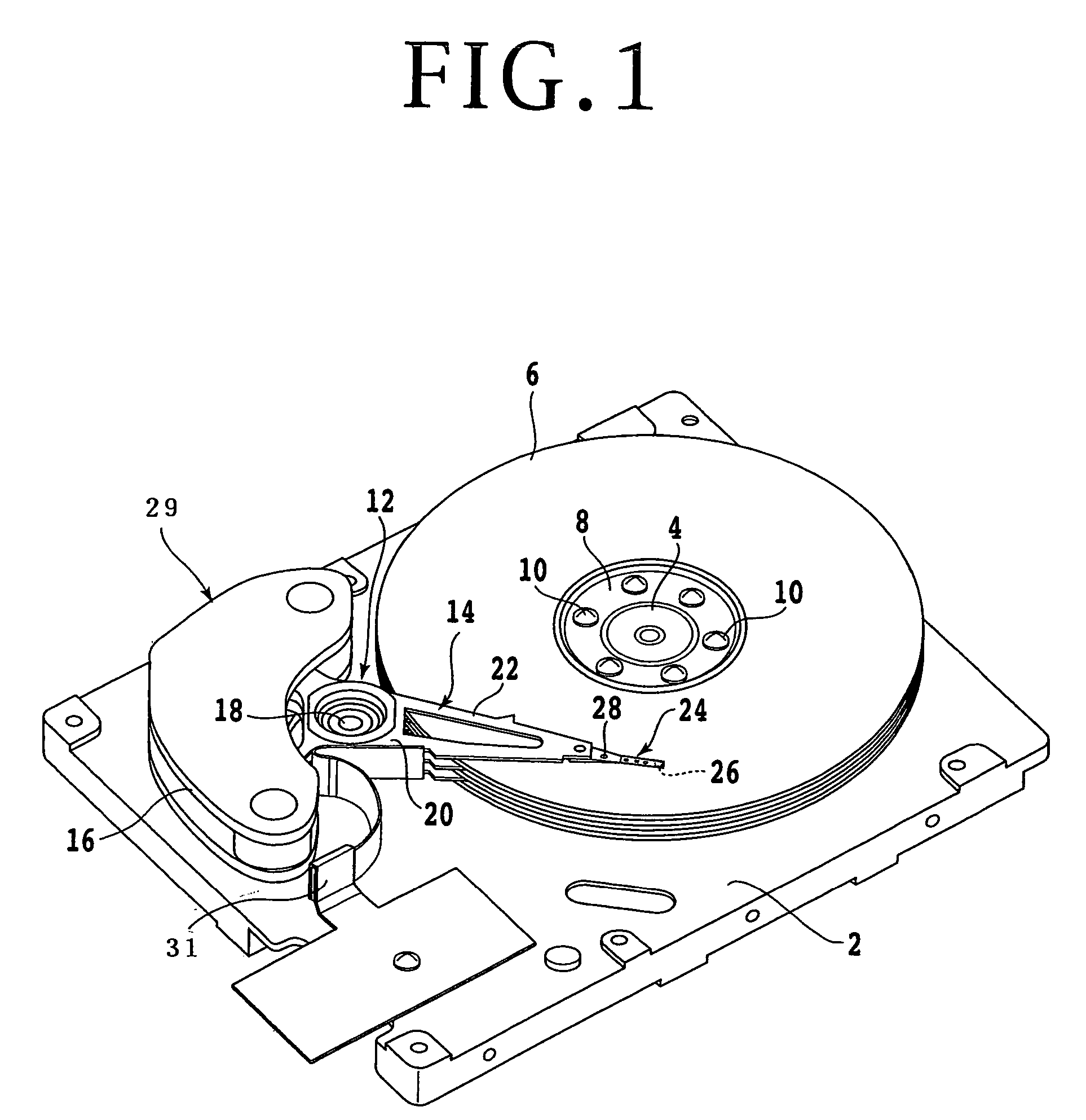
[0039] In the following, the present invention is described in detail with reference to the drawings. Referring to FIG. 1, there is shown a perspective view of a magnetic disk apparatus in a state wherein a cover is removed. A shaft 4 is secured to a base 2, and a spindle hub not shown which is driven to rotate by a DC motor is provided around the shaft 4. Magnetic disks 6 and spacers (not shown) are inserted alternately in the spindle hub, and a disk clamp 8 is fastened to the spindle hub by means of a plurality of screws 10 to attach the plurality of magnetic disks 6 in a spaced relationship by a predetermined distance from each other to the spindle hub.

[0040] Reference numeral 12 denotes a rotary actuator composed of an actuator arm assembly 14 and a magnetic circuit 16. The actuator arm assembly 14 is mounted for pivotal motion around a shaft 18 secured to the base 2. The actuator arm assembly 14 includes an actuator block 20 attached for rotation around the shaft 18 through a ...


PUM

PropertyMeasurementUnit
resonance frequencyaaaaaaaaaa
voltageaaaaaaaaaa
displacementaaaaaaaaaa

Abstract

A head assembly includes a suspension having a gimbal, a flexible printed wiring sheet having a plurality of conductor patterns and adhered to the suspension, first and second piezoelectric actuators mounted on the gimbal, and a head slider mounted on the first and second piezoelectric actuators. The first and second piezoelectric actuators are adhered to the gimbal at end portion adhesion portions symmetrical with respect to the center of pivotal motion thereof and are adhered to the head slider at end portion adhesion portions on the opposite side disposed symmetrically with respect to the center of pivotal motion similarly. Consequently, when a voltage is applied to the first and second piezoelectric actuators through the flexible printed wiring sheet, a couple of forces can be generated which vary the posture of the head slider only in one direction around the center of pivotal motion.

Description

[0001] This is a continuation of PCT International Application No. PCT / JP03 / 04855, filed Apr. 16, 2003, which was not published in English.BACKGROUND OF THE INVENTION [0002] 1. Field of the Invention [0003] This invention relates to a piezoelectric actuator used as a tracking actuator for a magnetic disk apparatus and a head assembly which uses the piezoelectric actuator. [0004] 2. Description of the Related Art [0005] In recent years, reduction in size and thickness of a magnetic disk apparatus which is a kind of external storage apparatus for computers has been and is proceeding, and further reduction in power consumption is demanded. Also increase in recording density and capacity of magnetic disk apparatus is demanded. Increase of the capacity of a magnetic disk apparatus can be achieved generally by increasing the recording capacity per one disk. However, if the recording capacity is increased without changing the diameter of the disk, then the track pitch decreases. Therefore,...

Claims


Application Information

Patent Timeline
Patent Type & Authority Applications(United States)
IPC IPC(8): G11B5/48G11B5/55G11B5/58G11B5/596G11B5/60G11B21/10G11B21/21H01L41/08H01L41/083H01L41/09
CPCG11B5/4853G11B5/5552G11B5/58H01L41/0477H01L41/338H01L41/0986H01L41/1875H01L41/273H01L41/083G11B5/483H10N30/877H10N30/50H10N30/206H10N30/8548H10N30/053H10N30/088
Inventor HIDA, MASAHARUMITA, TSUYOSHIKURIHARA, KAZUAKI
Owner FUJITSU LTD
Why Eureka
Try Eureka