Mould for simultaneously cooling inner and outer pipe walls of plastic pipe during molding

A technology for inner and outer pipes and plastic pipes is applied in the field of fittings and devices of plastic pipe production lines, which can solve the problems affecting the quality and use range of polyethylene plastic pipes, the decline of mechanical properties of pipes, and the uneven thickness of pipe walls, so as to overcome the phenomenon of brittle fracture, High production cost and improved uniformity

Inactive Publication Date: 2013-06-19
宜昌宜硕塑业有限公司
View PDF6 Cites 0 Cited by
  • Summary
  • Abstract
  • Description
  • Claims
  • Application Information

AI Technical Summary

Problems solved by technology

Sagging can cause uneven thickness of the pipe wall, which affects the quality and scope of use of polyethylene plastic pipes. How to improve the sagging phenomenon has been studied by domestic and foreign experts for many years. Some automatically adjust the die offset; some use oil (or water) to cool the die mandrel so that the core temperature is close to the crystallization temperature of polyethylene; some inject inert liquefied gas and cool it gently inside the pipe; some use Low temperature (minus 40 degrees) coolant cooling and so on, but there are more or less problems
[0004] 2. Internal stress: when the plastic pipe is produced, water cooling the surface of the plastic pipe will cause the outer surface of the pipe to shrink and solidify. Due to the poor thermal conductivity of polyethylene, when the inner wall gradually cools down and tends to shrink, it is stopped by the outer wall that is first cooled and solidified. The pipe will generate internal stress, resulting in a decrease in the mechanical properties of the pipe
Composite molds are also used to produce composite plastic pipes. During the molding process, the sum of the internal stresses formed by the outer layer and the inner layer is smaller than that of the same single-layer plastic pipe, but the effects of these methods are not ideal.

Method used


Image

  • Mould for simultaneously cooling inner and outer pipe walls of plastic pipe during molding
  • Mould for simultaneously cooling inner and outer pipe walls of plastic pipe during molding
  • Mould for simultaneously cooling inner and outer pipe walls of plastic pipe during molding

Examples


Embodiment Construction

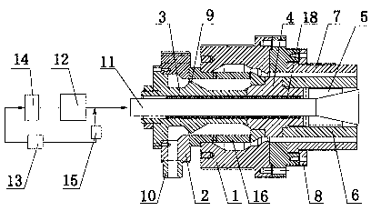
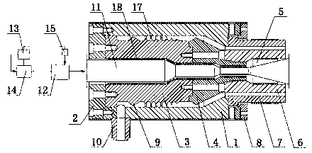
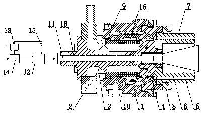
[0021] The mold in which the inner and outer pipe walls are cooled simultaneously when the plastic pipe is formed is composed of a mold body 1, a die head gland 2, a mandrel a3, a mandrel base 4, a mandrel b6, a die 7, a die gland 8, and a neck die 10. Mandrel a3 and mandrel holder 4 are housed in the mold body 1, filter screen cover 16 is made on the mandrel a3 of blue mold, and helix 17 is made on the mandrel a3 of spiral mould. The left end of mold body 1 is equipped with die head gland 2 and neck mold 10, and the right end of mold body 1 is equipped with core mold b6 and die 7, and die gland 8 is housed on the die 7. The center of described mandrel a3, mandrel seat 4 and mandrel b6 has through hole, and blowing duct 11 is housed in the through hole, and heat insulation layer 18 is equipped with in the blowing duct 11 outer layer, and the right end of blowing duct 11 is made with wind Road 5; a blower fan 12 is installed on the left side of the blowing duct 11, and a fan co...


PUM


Abstract

The invention relates to a mould for simultaneously cooling the inner and the outer pipe walls of a plastic pipe during molding, belonging to the technical field of accessory devices of a plastic pipe production line. The mould comprises a mould body, a core mould, a core mould base, a mouth mould, a neck mould and the like. The mould body is internally provided with the core mould and the core mould seat, and the core mould is provided with a strainer sleeve or a spiral body; and the left end of the mould body is provided with the neck mould, the right end of the mould body is provided with the core mould and the mouth mould, a blowing guide pipe is arranged in the centers of the core mould and the core mould base, the left side of the blowing guide pipe is provided with a fan, a fan frequency converter and an industrial control computer. When the mould for simultaneously cooling the inner and the outer pipe walls of the plastic pipe during molding is molded, melt flows through a shunt runner and are superposed layer by layer, and thus, not only are the melt and a lateral incipientfusion phenomenon improved through an elliptic structure of a distribution barrier, but also the inner pipe wall and the outer pipe wall are synchronously cooled by using the fan to blow natural wind onto the inner wall of a plastic pipe blank via the blowing guide pipe. Therefore, the problem that the outer wall of the plastic pipe always has internal stress and incipientfusion when water cooling is adopted in the prior art is solved, and the stress cracking resistance and the shock resistance of the plastic pipe are improved.

Description

technical field [0001] The invention relates to a mold for simultaneous cooling of inner and outer pipe walls when plastic pipes are formed, and belongs to the technical field of accessory devices for plastic pipe production lines. Background technique [0002] The production of large and thick-walled plastic pipes in the existing polyethylene generally has the following two major difficulties; [0003] 1. Sag: When the existing thick-walled polyethylene plastic pipes above DN315 are produced, water-cooled pipe blanks are used, and the radial solidification is cooled from the surface to the inside. However, due to the poor thermal conductivity of the plastic, the solidification process from the surface to the inside is very slow, resulting in the melt flowing along the inside of the pipe. This phenomenon is called sagging. Sagging can cause uneven thickness of the pipe wall, which affects the quality and scope of use of polyethylene plastic pipes. How to improve the sagging...

Claims


Application Information

Patent Timeline
Patent Type & Authority Patents(China)
IPC IPC(8): B29C33/04
Inventor 陈金宏陈镜杰陈估凡
Owner 宜昌宜硕塑业有限公司
Why Eureka
Try Eureka