Recording apparatus

a recording apparatus and recording head technology, applied in the field of recording apparatuses, can solve the problems of clogging the ink discharge orifice of the recording head, soot of the recording sheet, and above-described conventional examples

Inactive Publication Date: 2005-08-04
CANON KK
View PDF8 Cites 93 Cited by
  • Summary
  • Abstract
  • Description
  • Claims
  • Application Information

AI Technical Summary

Benefits of technology

[0017] The present invention has been made in light of the above problems, and accordingly can provide a recording apparatus capable of maintaining the distance between the recording head and recording face of the recording sheet (hereafter referred to as “head-sheet distance”) unchanged over the entire region from the leading edge of the recording sheet to the trailing edge thereof.
[0018] The present invention can also eliminate off-target landing of ink droplets as much as possible while preventing contact with the recording head, by generating cockling which occurs when a high-concentration image is recorded, not away from the recording head but toward the recording head, and also reducing the difference between the crests and troughs of the cockling (hereafter referred to as “P-P”, which is short for “peak-to-peak”).

Problems solved by technology

This is because in the event that the recording sheet floats up so far as to come into contact with the recording head, this not only leads to soiling of the recording sheet due to ink droplets on the recording head being transferred thereto and smearing of the unfixed ink on the recording sheet, but also causes trouble such as clogging of the ink discharge orifices of the recording head.
However, there are problems with the above-described conventional examples.
As a first problem, the shape of the waves and the depth of the troughs of the recording sheet change before and after the leading edge of the recording sheet reaches the wave holding spurs.
Also, the wave holding spurs 209 are rotatably borne by torsion coil springs 210 so as to be capable of elastic movement, and are capable of moving a certain amount in the height-wise direction, but this arrangement is originally intended for providing wave shapes to the recording sheets, and accordingly cannot completely eliminate the effects.
Consequently, the distance between the recording head and the recording face of the recording sheet changes before and after the leading edge of the recording sheet reaches the wave holding spurs, and with multi-pass recording wherein scanning of the recording head is repeated for multiple sheet feeds for forming an image, there have been problems such as the ink droplets landing off-target, offset in image colors, overall coarseness, and so forth.
However, this has negative effects as well, in that at portions where cockling occurs, the recording face of the recording sheet is distanced form the recording head, so the ink droplets land further off-target.
Consequently, there have been problems such as the ink droplets landing off-target, offset in image colors, overall coarseness, and so forth.

Method used


Image

  • Recording apparatus
  • Recording apparatus
  • Recording apparatus

Examples


first embodiment

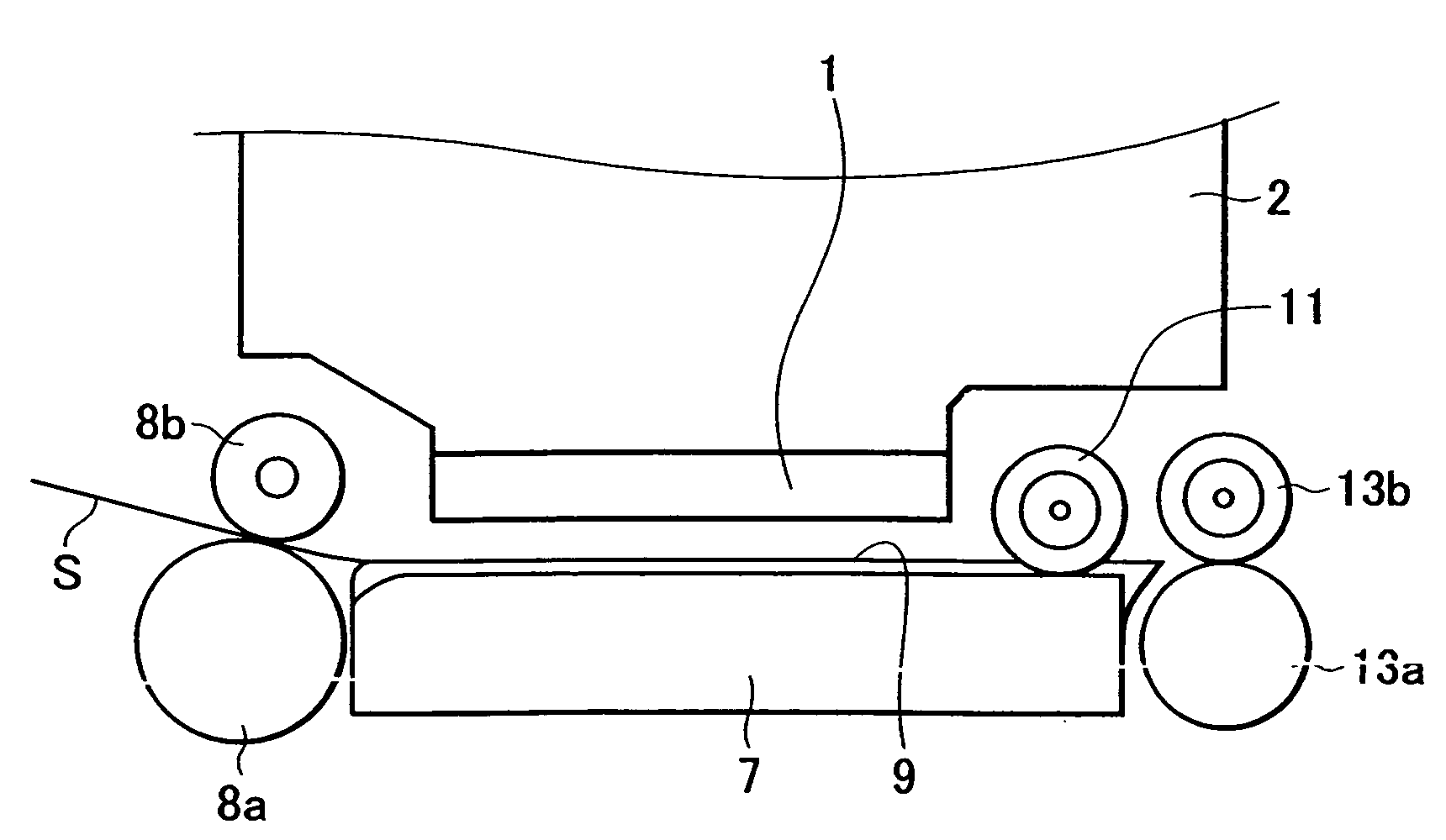
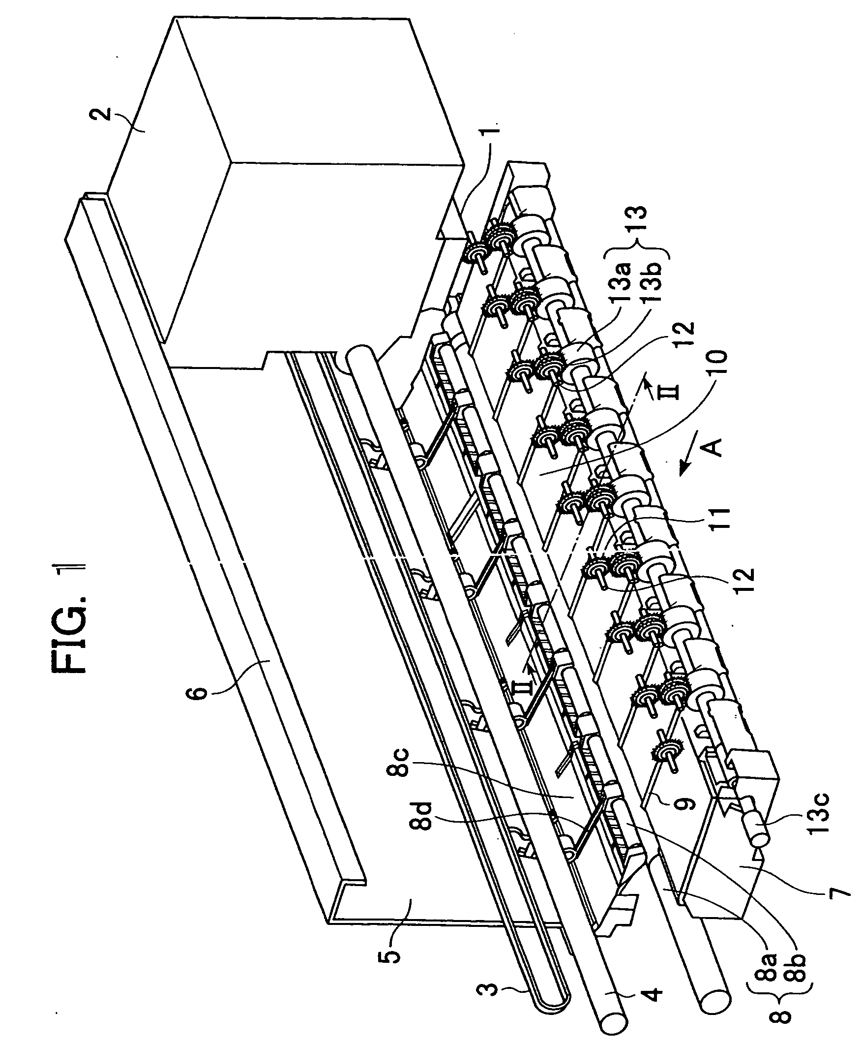
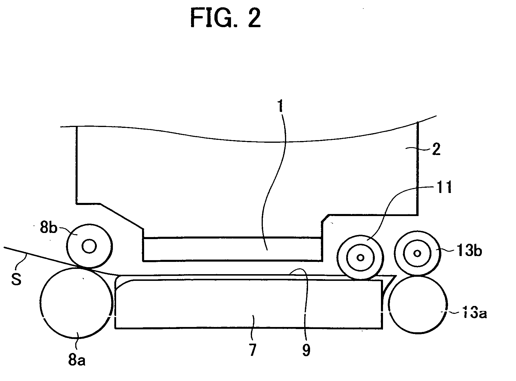
[0055] A recording apparatus according to a first embodiment of the present invention will now be described with reference to the drawings. FIG. 1 is a perspective view of the recording apparatus according to the present invention with a portion around the platen cut away, and FIG. 2 is a cross-section of that shown in FIG. 1 along line II-II.

[0056] In FIG. 1, a recording head 1 is mounted on a carriage 2, and the carriage 2 is driven by a carriage motor (not shown in the drawings) through a timing belt 3, so as to reciprocally scan over a platen 7 while supported by a guide rail 4 and a supporting rail 6 provided on a chassis 5.

[0057] A recording sheet S is transported to a nip position between a transporting roller pair 8 of a transporting roller 8a and a pinch roller 8b, where skewing and the like is corrected. This pinch roller 8b is under force of a pinch roller spring 8d through a pinch roller holder 8c so as to be pressed against the transporting roller 8a. Thus the pinch r...

second embodiment

[0076] While the first embodiment only had the wave holding spurs 11 pressed against the grooves 10 as spurs disposed above the platen 7, with the present embodiment, ridge spurs 14 are also disposed on the ridges 9 in addition to the wave holding spurs 11 as shown in FIG. 4. The ridge spurs 14 are disposed in generally the same position as the wave holding spurs 11 in the direction of transportation, rotatably supported on the center of rotation thereof by torsion coil springs 15, and pressed against the ridges 9. Due to such a configuration, unrecorded recording sheets and recording sheets where little swelling has occurred can be pressed against the ridges 9 in a more sure manner, and sheets with cockling can have the number of crests doubled before reaching the sheet discharge roller pairs 13.

third embodiment

[0077] This embodiment has notches 7a formed in the platen 7 as shown in FIG. 5, with the sheet discharge roller pairs 13 disposed at the position of the notches 7a. Thus, the sheet discharge roller pairs 13 are at generally the same position in the transportation direction as the wave holding spurs 11.

[0078] However, in this case, the transporting spurs 13b need to be offset upstream in the transportation direction as to the sheet discharge rollers 13a, so as to press the trailing edge of the recording sheet in the direction of the platen 7, in order to prevent floating following the trailing edge of the recording sheet passing the transporting roller pair 8. The configuration of the present embodiment allows the depth-wise length to be reduced, thereby conserving space.


PUM


Abstract

Ridges and grooves are alternately formed on a platen in the direction of transporting sheets. Wave holding spurs are rotatably supported by torsion springs downstream of a recording area, and pressed against the grooves. Sheet discharge roller pairs are disposed generally downstream from the grooves. Recording sheets exhibit cockling which rises up toward a recording head due to swelling from ink, but a substantial amount of the swelling is contained in the grooves, so the cockling does not come into contact with the recording head, and further, the peak-to-peak distance of the wave shapes of the recording sheets can be reduced. Following the leading edge of a recording sheet passing the sheet discharge roller pairs, the crests of the cockling are collapsed by transporting spurs and divided between wave holding spurs and the transporting spurs, and thus the peak-to-peak distance is further reduced, consequently preventing off-target landing of ink droplets.

Description

BACKGROUND OF THE INVENTION [0001] 1. Field of the Invention [0002] The present invention relates to an apparatus for recording on sheets with recording means, and particularly relates to the configuration of a particular part of an ink jet recording apparatus which records by discharging ink droplets from ink jet recording means, the part being the printing region and the areas upstream and downstream therefrom. [0003] 2. Description of the Related Art [0004] In order to record with ink jet recording apparatuses in a stable manner, the effects of wrinkling and undulations (hereafter referred to as “cockling”) upon ink being applied to recording sheets serving as a recording medium must be eliminated as much as possible, and also recording sheets which tend to curl due to the effects of humidity and the like must be kept from floating toward the head, so as to maintain the distance between the surface of the recording sheet and the recording head. This is because in the event that t...

Claims


Application Information

Patent Timeline
Patent Type & Authority Applications(United States)
IPC IPC(8): B41J11/00B41J2/01B41J11/02B41J11/06B41J13/02B41J13/14B65H29/22B65H29/70
CPCB41J11/005B41J13/14B41J11/06
Inventor OHYAMA, KAZUO
Owner CANON KK
Why Eureka
Try Eureka