Recording apparatus
a recording apparatus and recording head technology, applied in the field of recording apparatuses, can solve the problems of clogging the ink discharge orifice of the recording head, soot of the recording sheet, and above-described conventional examples
- Summary
- Abstract
- Description
- Claims
- Application Information
AI Technical Summary
Benefits of technology
Problems solved by technology
Method used
Image
Examples
first embodiment
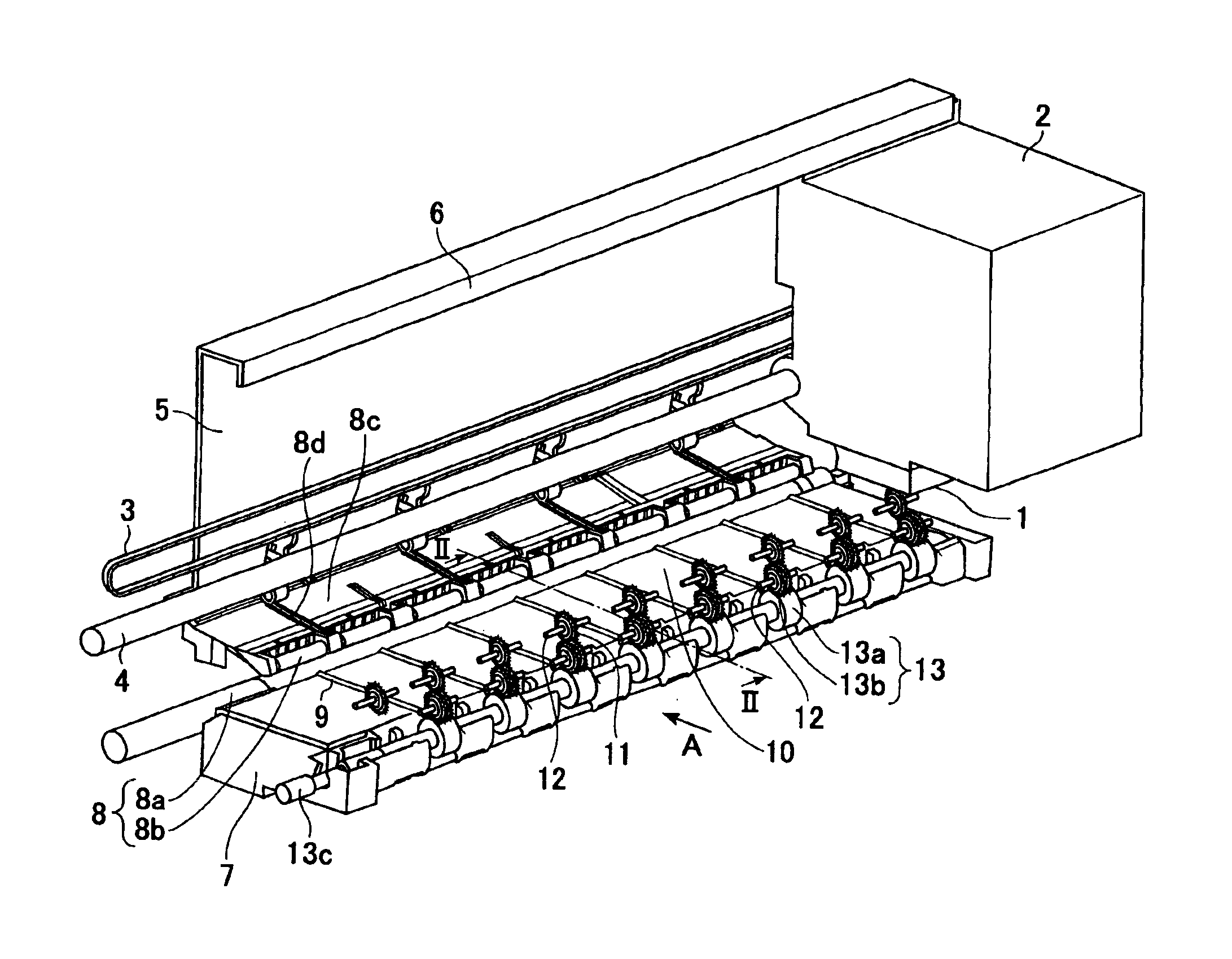
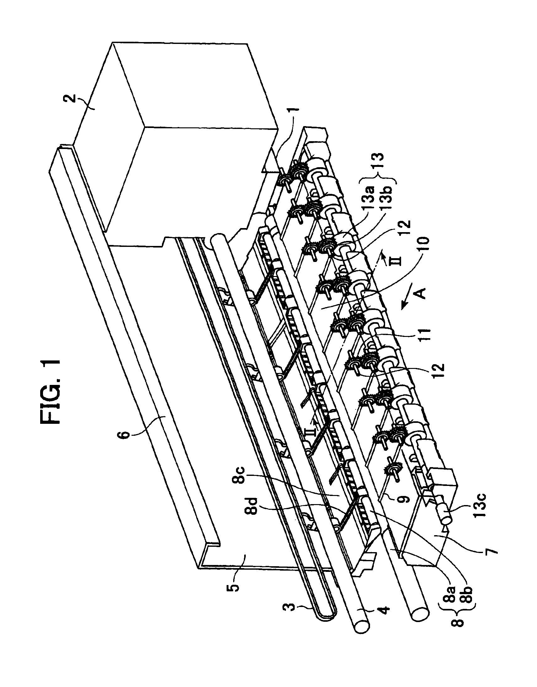
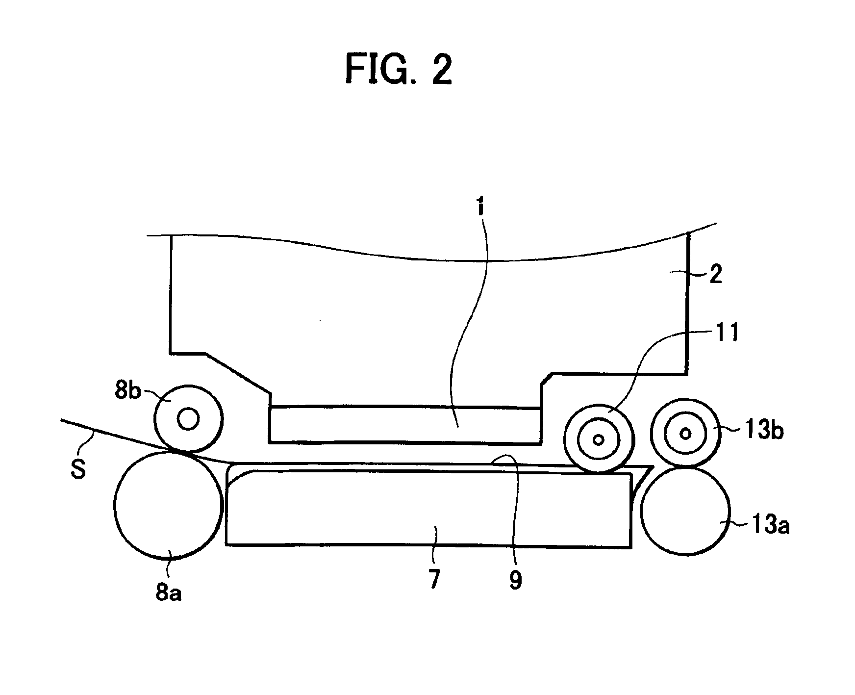
[0055]A recording apparatus according to a first embodiment of the present invention will now be described with reference to the drawings. FIG. 1 is a perspective view of the recording apparatus according to the present invention with a portion around the platen cut away, and FIG. 2 is a cross-section of that shown in FIG. 1 along line II—II.
[0056]In FIG. 1, a recording head 1 is mounted on a carriage 2, and the carriage 2 is driven by a carriage motor (not shown in the drawings) through a timing belt 3, so as to reciprocally scan over a platen 7 while supported by a guide rail 4 and a supporting rail 6 provided on a chassis 5.
[0057]A recording sheet S is transported to a nip position between a transporting roller pair 8 of a transporting roller 8a and a pinch roller 8b, where skewing and the like is corrected. This pinch roller 8b is under force of a pinch roller spring 8d through a pinch roller holder 8c so as to be pressed against the transporting roller 8a. Thus the pinch roller...
second embodiment
[0076]While the first embodiment only had the wave holding spurs 11 pressed against the grooves 10 as spurs disposed above the platen 7, with the present embodiment, ridge spurs 14 are also disposed on the ridges 9 in addition to the wave holding spurs 11 as shown in FIG. 4. The ridge spurs 14 are disposed in generally the same position as the wave holding spurs 11 in the direction of transportation, rotatably supported on the center of rotation thereof by torsion coil springs 15, and pressed against the ridges 9. Due to such a configuration, unrecorded recording sheets and recording sheets where little swelling has occurred can be pressed against the ridges 9 in a more sure manner, and sheets with cockling can have the number of crests doubled before reaching the sheet discharge roller pairs 13.
third embodiment
[0077]This embodiment has notches 7a formed in the platen 7 as shown in FIG. 5, with the sheet discharge roller pairs 13 disposed at the position of the notches 7a. Thus, the sheet discharge roller pairs 13 are at generally the same position in the transportation direction as the wave holding spurs 11.
[0078]However, in this case, the transporting spurs 13b need to be offset upstream in the transportation direction as to the sheet discharge rollers 13a, so as to press the trailing edge of the recording sheet in the direction of the platen 7, in order to prevent floating following the trailing edge of the recording sheet passing the transporting roller pair 8. The configuration of the present embodiment allows the depth-wise length to be reduced, thereby conserving space.
PUM
 Abstract
Description
Claims
Application Information
 - R&D
- Intellectual Property
- Life Sciences
- Materials
- Tech Scout
- Unparalleled Data Quality
- Higher Quality Content
- 60% Fewer Hallucinations
Browse by: Latest US Patents, China's latest patents, Technical Efficacy Thesaurus, Application Domain, Technology Topic, Popular Technical Reports.
© 2025 PatSnap. All rights reserved.Legal|Privacy policy|Modern Slavery Act Transparency Statement|Sitemap|About US| Contact US: help@patsnap.com


