Walking brace

a brace and walking technology, applied in the field of orthopaedic devices, can solve problems such as even more difficult walking, and achieve the effect of improving user comfor

Inactive Publication Date: 2005-08-04
DJO
View PDF40 Cites 100 Cited by
  • Summary
  • Abstract
  • Description
  • Claims
  • Application Information

AI Technical Summary

Benefits of technology

[0013] The present invention comprises a walking brace for immobilizing and / or protecting the lower leg of a patient, the brace comprising a leg portion adapted to fit substantially around the lower leg of a patient and a sole portion that fits beneath the patient's foot. The sole portion is provided with a dual layer of resilient shock absorbing material disposed along its bottom surface. The dual layer comprises an upper layer of a relatively softer material and a lower layer of a relatively more durable material. The sole portion of the leg brace is provided with an opening in the area of the user's heel such that the patient's heel contacts the upper layer of the dual layer of resilient shock absorbing material when the patient walks. The dual layer can provide good shock absorbency but can be made thinner to provide a lower profile. The foot of the injured limb will not be raised as height with respect to the foot of the uninjured limb as in prior art braces, for greater patient comfort during walking.

Problems solved by technology

Some patients experience difficulty or discomfort when using a walking brace because the foot of the injured leg is raised relative to the foot of the uninjured leg such that the patient's legs are effectively two different lengths, thereby making walking even more difficult.
Another issue relating to patient comfort and compliance is the ease of access to adjustable air cells in the device.
Yet another issue relating to patient comfort is the fit of the upper end of the leg portion around the patient's ankle and calf.

Method used


Image

  • Walking brace
  • Walking brace
  • Walking brace

Examples


Embodiment Construction

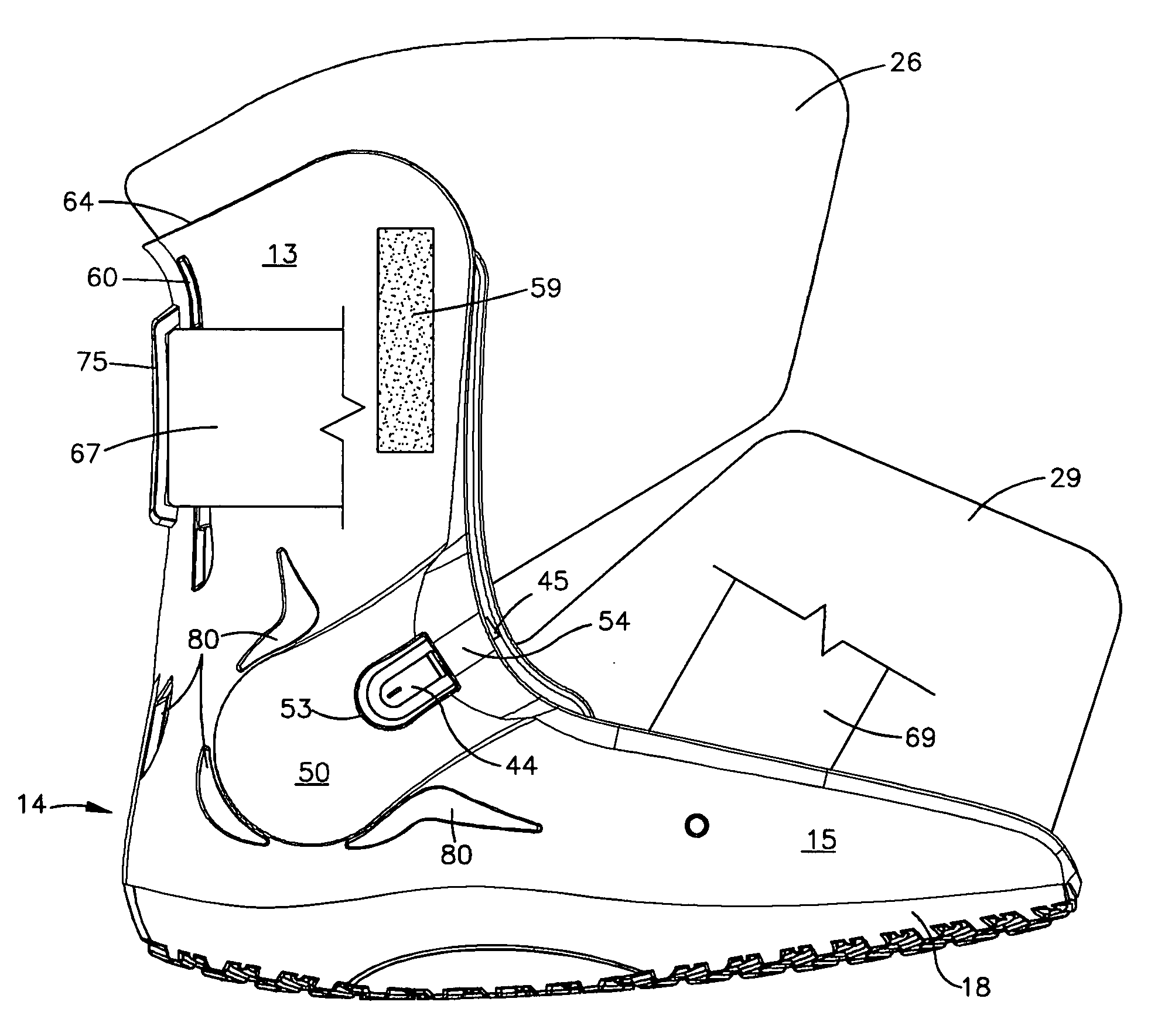
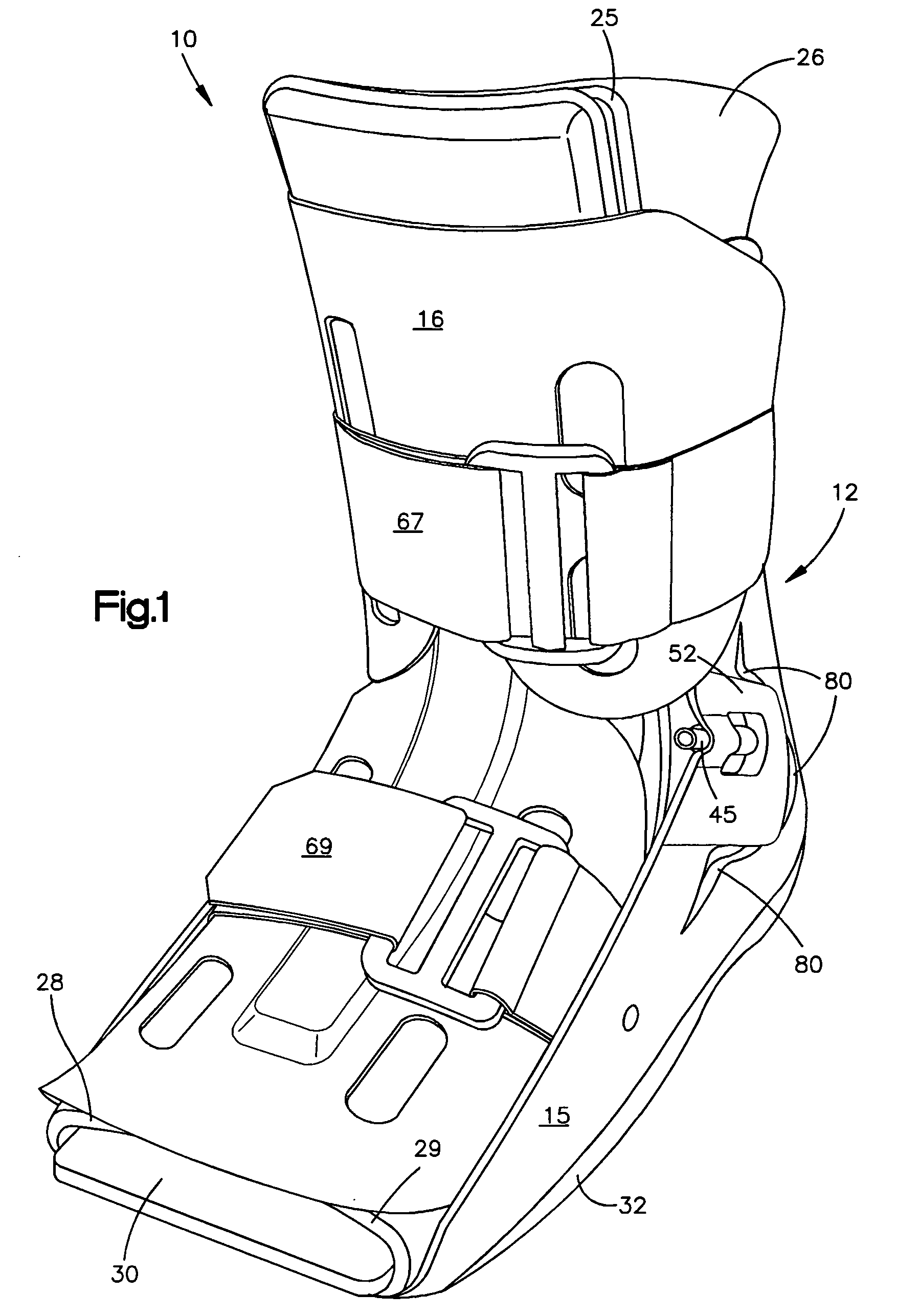
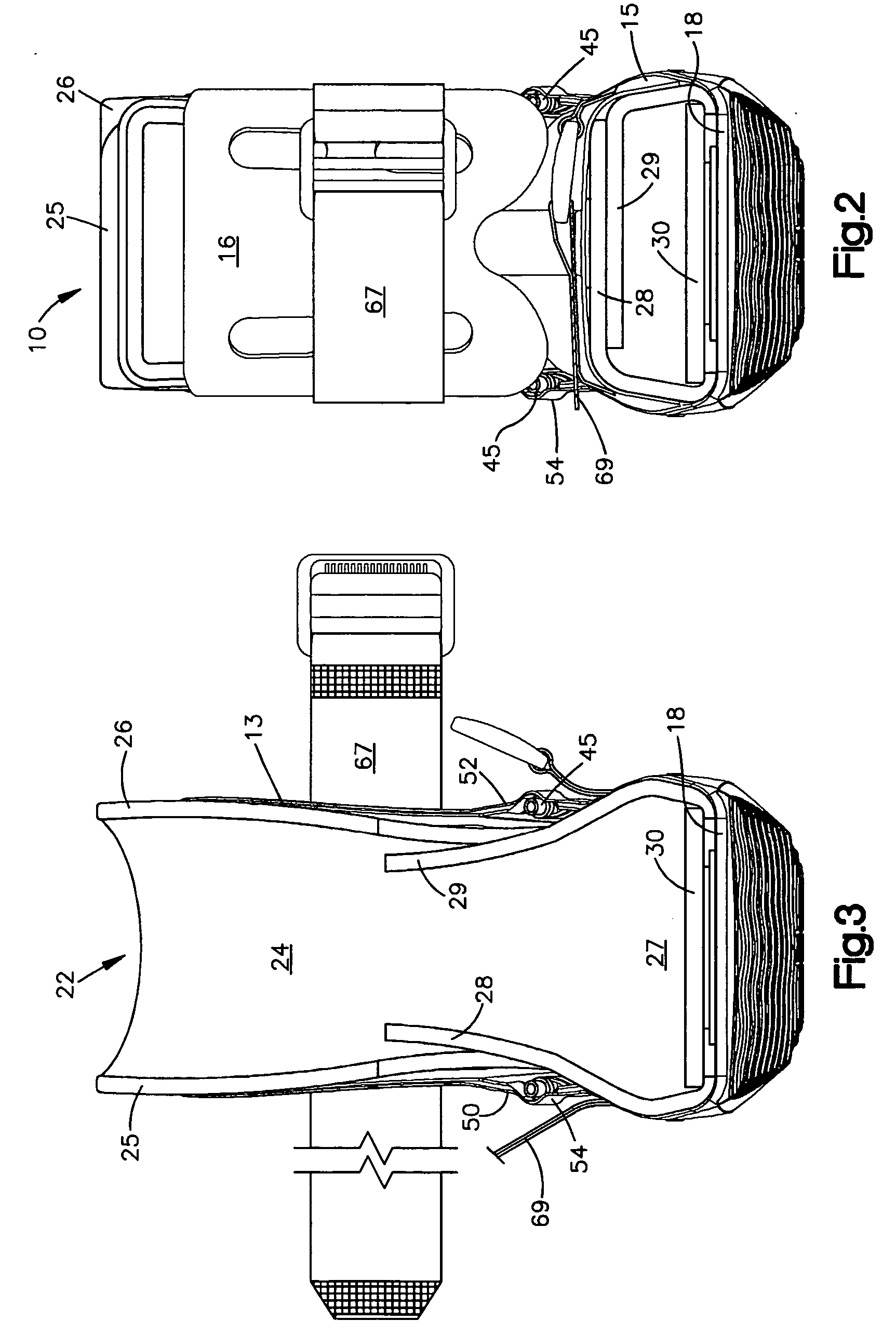
[0027] Referring to the figures, a preferred embodiment of a walking brace 10 of the present invention includes a rigid exterior shell 12 comprising a rear portion 14 and a front shell portion 16. Rear portion 14 includes leg portion 13 and foot portion 15. Leg portion 13 of rear portion 14 is adapted to fit around the anterior surface and sides of the patient's lower leg. Disposed below foot portion 15 is sole 18. Foot portion 15 and sole portion 18 are adapted to fit around the sides and bottom of the patient's foot. Disposed along the interior surfaces of rear portion 14 is a foam liner 22, preferably of an open cell foam material. Foam liner comprises a leg portion 24 that includes two forwardly extending flaps 25 and 26 that wrap about the front of the lower leg, and a foot portion 27 that includes two upwardly extending flaps 28 and 29 that wrap generally over the top of the patient's foot. Foam liner 22 can be secured to rear portion 14 of exterior shell 12 by known fastening...


PUM


Abstract

A walking brace for immobilizing and / or protecting the lower leg of a patient comprises a leg portion adapted to fit substantially around the lower leg of a patient and a sole portion that fits beneath the patient's foot. The sole portion is provided with a dual layer of resilient shock absorbing material disposed along its bottom surface. The dual layer comprises an upper layer of a relatively softer material and a lower layer of a relatively more durable material. The dual layer can provide good shock absorbency but can be made thinner to provide a lower profile. In another aspect of the invention, the walking brace is provided with one or more inflatable air cells to provide adjustable therapeutic pressure to the leg and the leg portion of the brace is in the form of a rigid shell provided with a protruding region for receiving the air cell outlet associated with each air cell such that the air cell outlet is directed toward the front of the walking brace for easy access by the user. In yet another aspect of the invention, the rigid shell member of the leg portion is provided with one or more longitudinal slits that allow expansion of the leg portion to accommodate an enlarged lower leg portion of a patient. The expanded leg portion can accommodate users with enlarged lower limbs, such as those suffering from severe edema.

Description

FIELD OF THE INVENTION [0001] The present invention relates generally to orthopedic devices, and more particularly, to those orthopedic devices known variously as casts, splints, braces, etc. which are especially adapted for immobilizing and / or protecting injured limbs or other parts of the anatomy. DESCRIPTION OF THE RELATED ART [0002] In the management of certain injuries to the lower extremities such as fractures of the tibia and fibula, malleolar fractures, or severe ankle sprains, it is common to immobilize the lower extremity completely by use of the well-known molded plastic or resin cast. Once the injured extremity has become stable, however, it has been found that recovery may be effected more rapidly by gradually and progressively permitting the extremity to bear weight and undergo other permitted exercises. [0003] For example, an orthopedic brace, such as that disclosed in U.S. Pat. No. 3,955,565, which is assigned to the assignee herein and incorporated herein by referen...

Claims


Application Information

Patent Timeline
Patent Type & Authority Applications(United States)
IPC IPC(8): A61F5/01
CPCA61F5/012A61F5/0111
Inventor PICK, EREZ
Owner DJO
Why Eureka
Try Eureka