
Gutter deflector shield

Inactive Publication Date: 2005-08-11
GUTTER DEFENDER
View PDF14 Cites 31 Cited by
  • Summary
  • Abstract
  • Description
  • Claims
  • Application Information

AI Technical Summary

Benefits of technology

[0013] In accordance with the present invention, the apparatus includes a deflector configuration constructed to cooperate with a flange-like portion provided on a gutter support strap or hanger to allow simple installation of several lengths of the deflector or shield portions adjacent to one another to properly cover the length of the gutter and fix it against vertical separation from its position over the gutter. Such undesirable vertical separation can occur during high wind storms wherein an upward force is directed to the deflector shield which may cause a disconnection of the deflector or shield portion from its intended functional position overlying the gutter.
[0017] When mated, these flanges permit limited relative slideable movement of each length of the deflector shield relative to the support strap and enhances the ease of installation of the deflector shield.
[0018] As a further aspect of the present invention, a gutter deflector manufactured according to the present invention is relatively simple in design to allow for inexpensive manufacture employing common, well-known materials and is substantially maintenance free relative to requiring manually cleaning debris out of the gutter trough which tends to clog the gutter system and disrupt its intended function.

Problems solved by technology

Such undesirable vertical separation can occur during high wind storms wherein an upward force is directed to the deflector shield which may cause a disconnection of the deflector or shield portion from its intended functional position overlying the gutter.
In prior art devices, if this latter condition develops, water flowing down the deflector surface tends to flow over such points of blockage and then beyond the front lip of the gutter, thereby compromising the intended performance of the gutter.

Method used


Image

  • Gutter deflector shield
  • Gutter deflector shield
  • Gutter deflector shield

Examples


Embodiment Construction

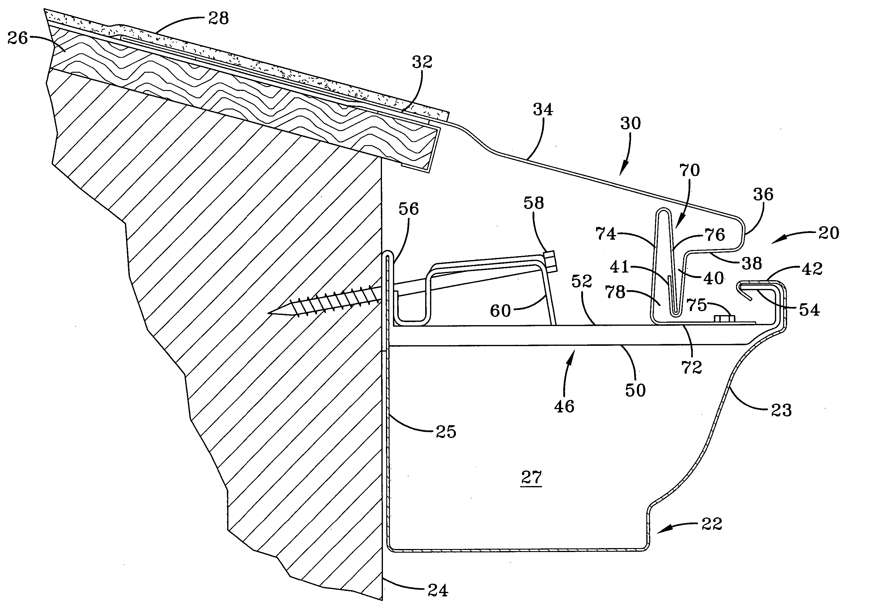
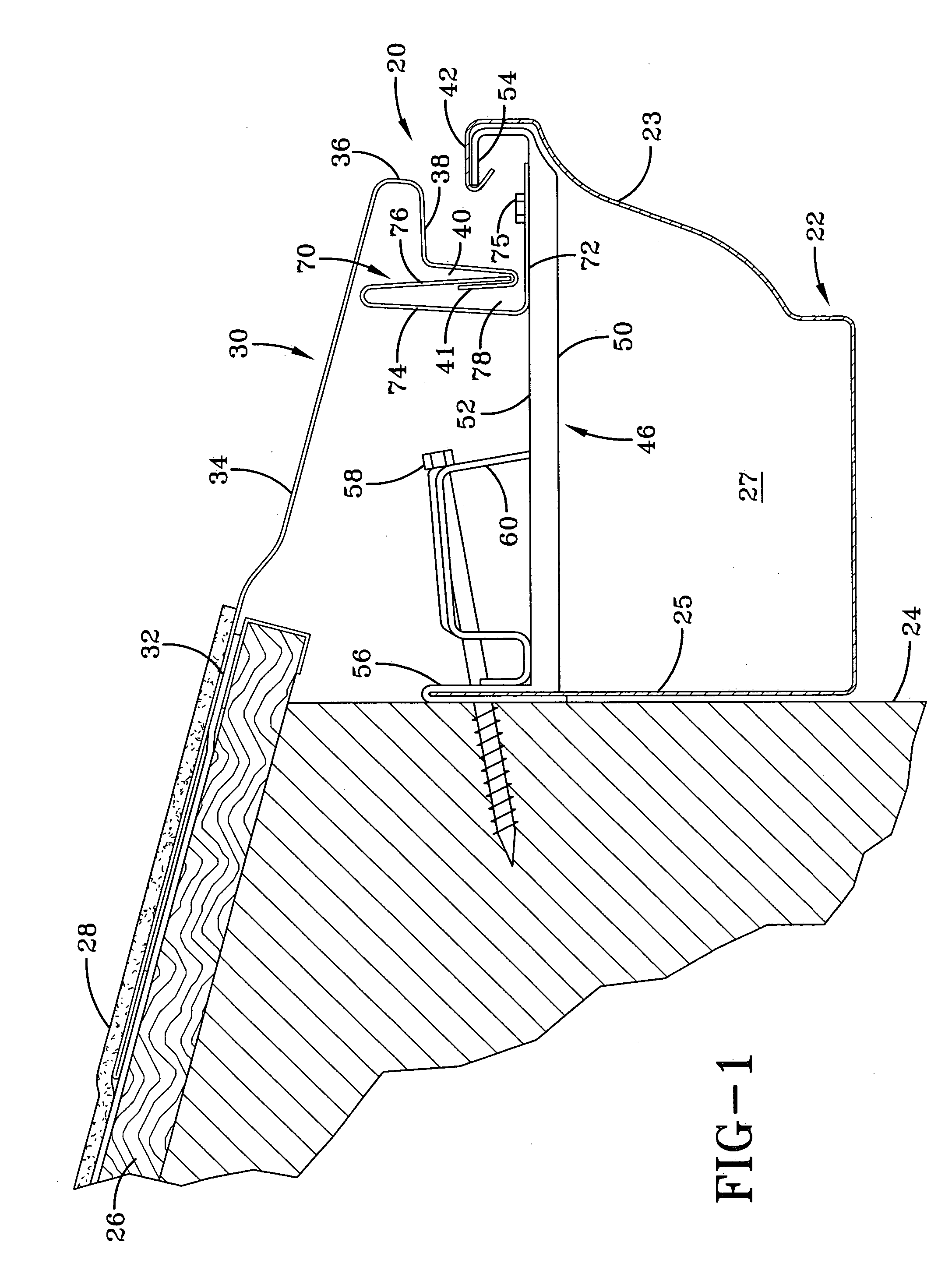
[0023] A preferred gutter deflector apparatus, indicated generally at 20, constructed in accordance with the present invention is illustrated in FIG. 1 mounted to a conventional gutter 22 of a building 24 having a slanted roof 26 covered with conventional shingles 28.

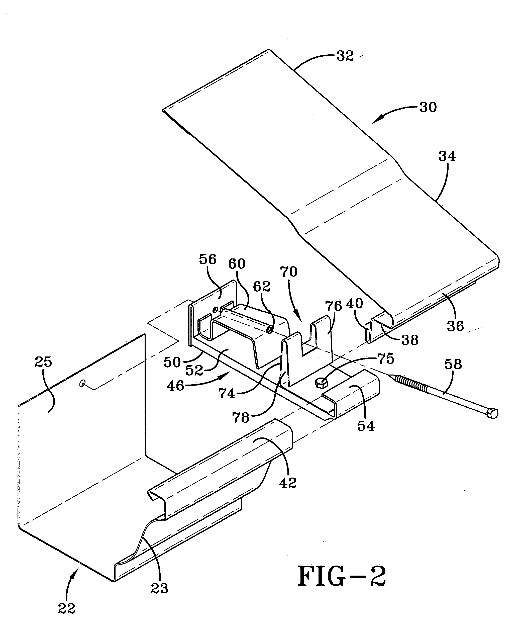
[0024] The deflector shield portion, indicated generally at 30, includes a rear portion 32 which conventionally slides under the outermost layer of shingles 28, a central portion 34 which extends outwardly to a point in a vertical plane over at least a portion of the forward lip 42 of gutter 22, and a front portion 36 provided with a reverse curve section 38 which terminates in an upwardly facing generally U or V-shaped opening 40.

[0025] If deemed necessary, central portion 34 may be provided with ribs, or curved sections, or other features which have the function to attenuate or modify the flow of water over the deflector surface to reduce any tendency for the flow of water to overcome surface tension. The latter is ...


PUM


Abstract

A deflector shield apparatus for rain gutters to prevent leaf and similar debris from entering the trough portion of the gutter. The deflector shield apparatus includes means for mounting the deflector to the gutter and associated building structure to provide improved function of the gutter system and easy installation. The deflector shield comprises a rigid sheet material having a rear portion adapted to be mounted under the outermost row of roof shingles, a central portion extending outward over the gutter, and a forward portion provided with a downturned curve forming a nose disposed over the front lip of the gutter and a reverse curved terminal and extending rearwardly over the trough portion of the gutter. Included in the apparatus is a modified gutter support strap having opposing ends in engagement with the front and rear wall of the gutter and means to connect the rear wall of the gutter to the associated building wall. The support strap also includes a vertically extending flange configured to cooperate with a downwardly extending flange formed on the terminal end of the reversed curved portion of the forward portion of the deflector shield to fix the gutter shield in position yet from a continuous, open space between the forward nose of the deflector and the front lip of the gutter.

Description

BACKGROUND OF THE INVENTION [0001] 1. Field of the Invention [0002] This invention relates to rain gutters and shield apparatus to permit water to flow into the gutter while deflecting debris from entering the gutter. [0003] 2. Description of the Related Art [0004] The collection of leaves and other similar debris in rain gutters is an old and well-recognized problem which causes downspouts to clog. This interferes with the intended performance of the rain gutter. The maintenance required from time to time to clean debris from gutters is considerable and is highly undesirable. [0005] A great number of gutter shield devices have been priorly proposed and several are presently marketed which are directed to solving this problem. One form of such shields is a screen or screen-like device wherein water is directed into the gutter through a screen or plurality of small openings aligned over the trough portion of the gutter and the larger debris is prevented from entry into the gutter. Ho...

Claims


Application Information

Patent Timeline
IPC IPC(8): E04D13/076
CPCE04D13/076
Inventor RILEY, PHILIP D.CHRISTY, JEFFREY A.
Owner GUTTER DEFENDER
Learn More