System and method for transporting MPEG2TS in RTP/UDP/IP

a technology of mpeg2 video data and transport system, applied in the field of compressed video communication, can solve the problems of affecting picture quality, affecting storage and transmission delay, damage to picture quality, etc., and achieve the effect of reducing the jitter of variable transmission delay

Inactive Publication Date: 2005-08-11
SHARP KK
View PDF6 Cites 231 Cited by
  • Summary
  • Abstract
  • Description
  • Claims
  • Application Information

AI Technical Summary

Benefits of technology

[0012] Accordingly, a method is provided for receiving an MPEG2 transport stream (TS) in a real-time protocol (RTP) / user datagram protocol (UDP) / Internet protocol (IP) packet. The method comprises: receiving an IP packet via an IP network, having a variable transmission delay; accessing a timestamp carried in a RTP packet; linking the timestamp with a program clock reference (PCR) MPEG2TS carried in the RTP packet payload; and, using the timestamp to eliminate variable transmission delay jitter, associated with the PCR MPEG2TS.

Problems solved by technology

Fluctuations of the synthesized color sub-carrier cause an impairment of the picture quality.
If a free-running decoder is installed in a personal computer (PC), it may be subject to overflow or underflow, which also damages picture quality.
However, when MPEG video is transmitted via an Internet Protocol (IP) network, the storage and transmission delays may vary.
There is no requirement that MPEG2 packets be transported per a schedule, and the loading and buffering of IP packets before transmission cannot be predetermined.
Route change and variation is another contributor to IP network jitter.
As a result, the overall delay, from Video In to Video Out, varies and the system timing requirements cannot always be met.
Further, the 32-bit RTP timestamp only has a resolution of 90 kilohertz (kHz), insufficient for a 500 ns systems requirement.

Method used


Image

  • System and method for transporting MPEG2TS in RTP/UDP/IP
  • System and method for transporting MPEG2TS in RTP/UDP/IP
  • System and method for transporting MPEG2TS in RTP/UDP/IP

Examples


Embodiment Construction

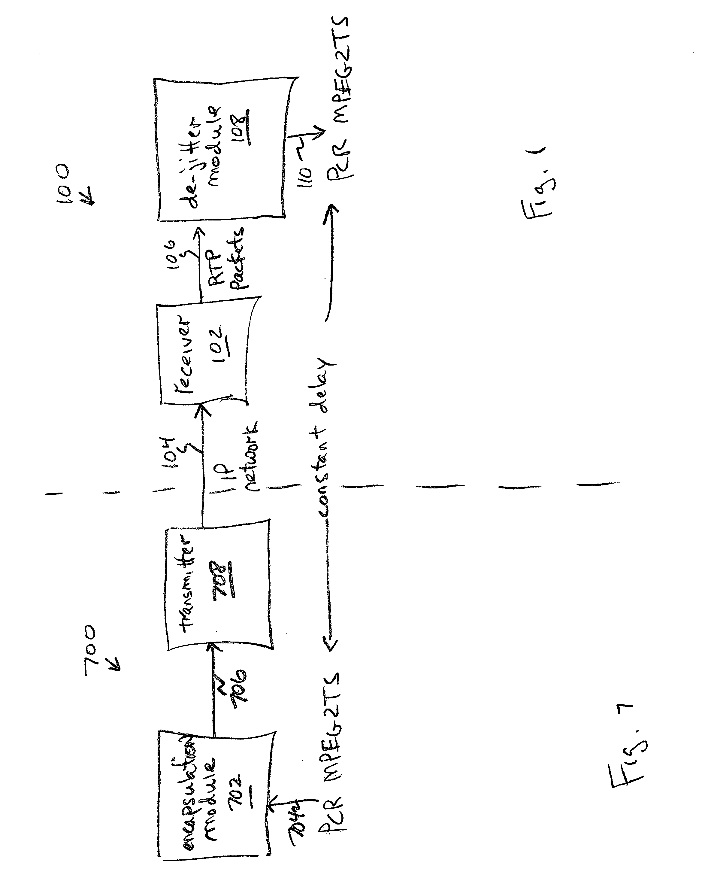
[0030]FIG. 1 is a schematic block diagram of the present invention system for receiving an MPEG2TS in a RTP / UDP / IP packet. The system 100 comprises a receiver 102 having an IP network interface to receive an IP packet via an IP network on line The IP network has an inherent variable transmission delay. The variable transmission delay problem associated with real-time IP communications has been described in the Background Section, above, and as is understood by those skilled in the art. The receiver 102 has an interface on line 106 to supply a RTP packet. For simplicity, it is assumed that the receiver 102 disassembles the IP packet payloads into RTP packets.

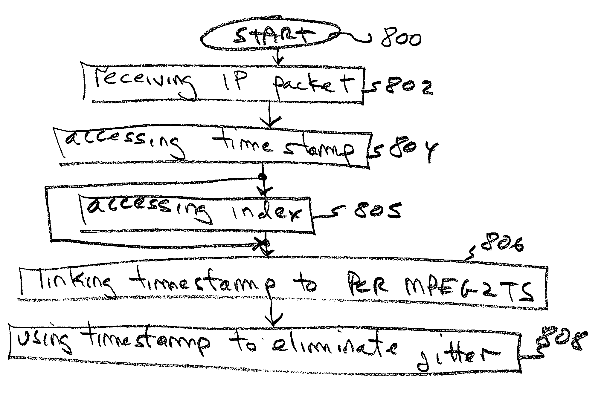
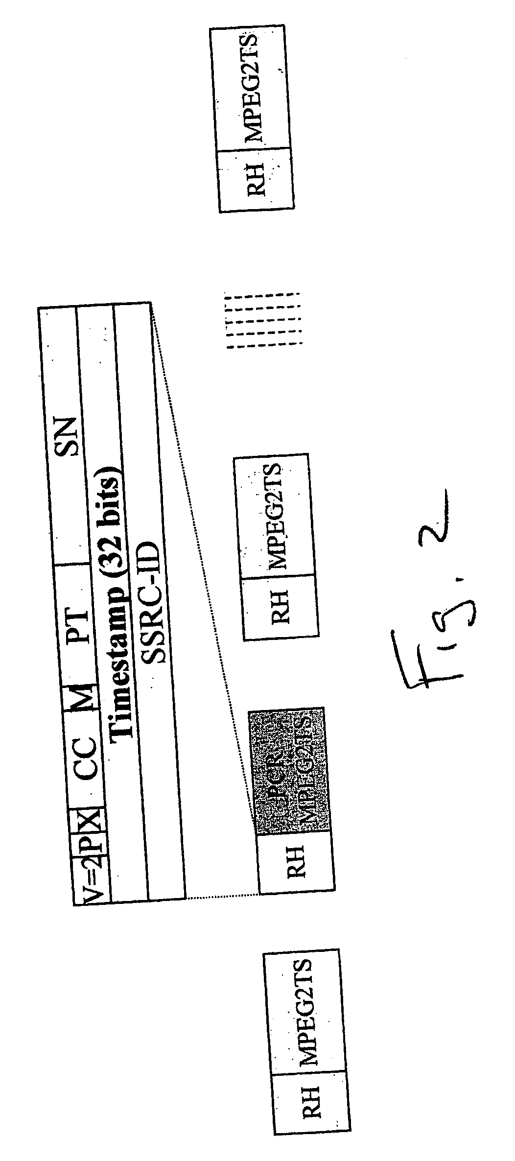
[0031] A de-jitter module 108 has an interface on line 106 to accept the RTP packet. The de-jitter module 108 accesses a timestamp carried in a RTP packet, and links the timestamp with a program clock reference (PCR) MPEG2TS carried in the RTP packet payload. The de-jitter module 108 uses the timestamp to eliminate variable tran...


PUM


Abstract

Systems and methods are provided for receiving and transmitting an MPEG2 transport stream (TS) in a real-time protocol (RTP)/user datagram protocol (UDP)/Internet protocol (IP) packet. The receiving method comprises: receiving an IP packet via an IP network, having a variable transmission delay; accessing a timestamp carried in a RTP packet; linking the timestamp with a program clock reference (PCR) MPEG2TS carried in the RTP packet payload; and, using the timestamp to eliminate variable transmission delay jitter, associated with the PCR MPEG2TS. In one aspect of the method, the timestamp has a resolution of greater than 500 nanoseconds (ns), so that the variable transmission delay jitter, associated with the PCR MPEG2TS can be reduced to a jitter of less than 500 ns.

Description

BACKGROUND OF THE INVENTION [0001] 1. Field of the Invention [0002] This invention generally relates to the communications of compressed video and, more particularly, to a system and method for minimizing jitter in MPEG2 video data communicated via an Internet Protocol (IP) network. [0003] 2. Description of the Related Art [0004] The National Television Standards Committee (NTCS) / Phase Alternation by Line (PAL) timing requirements associated with motion pictures expert group (MPEG)2 video communications are very stringent. Fluctuations of the synthesized color sub-carrier cause an impairment of the picture quality. Thus, for a broadcast-level video system, the system frequency requirements might be as tight as + / −3 parts per million (PPM). If a free-running decoder is installed in a personal computer (PC), it may be subject to overflow or underflow, which also damages picture quality. [0005]FIG. 10 is a diagram illustrating the transport of the program clock reference (PCR) used in ...

Claims


Application Information

Patent Timeline
Patent Type & Authority Applications(United States)
IPC IPC(8): G06F15/16
CPCH04N21/242H04N21/4305H04L65/608H04N21/6437H04N21/64322H04L65/65
Inventor XU, SHUGONG
Owner SHARP KK
Why Eureka
Try Eureka