Fuel injection controller for engine

a technology of fuel injection controller and engine, which is applied in the direction of electric control, speed sensing governor, machines/engines, etc., can solve the problems of difficult to lower the target speed with this controller, engine stalls, engine stalls, etc., and achieve the effect of lowering the target speed

Inactive Publication Date: 2005-08-18
TOYOTA JIDOSHA KK
View PDF9 Cites 106 Cited by
  • Summary
  • Abstract
  • Description
  • Claims
  • Application Information

AI Technical Summary

Benefits of technology

[0009] For an engine having a direct injector and an intake injector, it is an object of the present invention to provide a fuel injection controller which is capable of lowering the target speed while preventing the engine from stalling when the engine is idling.

Problems solved by technology

However, when the target speed is set to a lower value, the engine is prone to stall.
In this controller, however, the engine may stall if the target speed is reduced.
Therefore, it is difficult to lower the target speed with this controller.

Method used


Image

  • Fuel injection controller for engine
  • Fuel injection controller for engine
  • Fuel injection controller for engine

Examples


Embodiment Construction

[0023] A fuel injection controller according to a preferred embodiment of the present invention will now be described with reference to FIGS. 1 through 8.

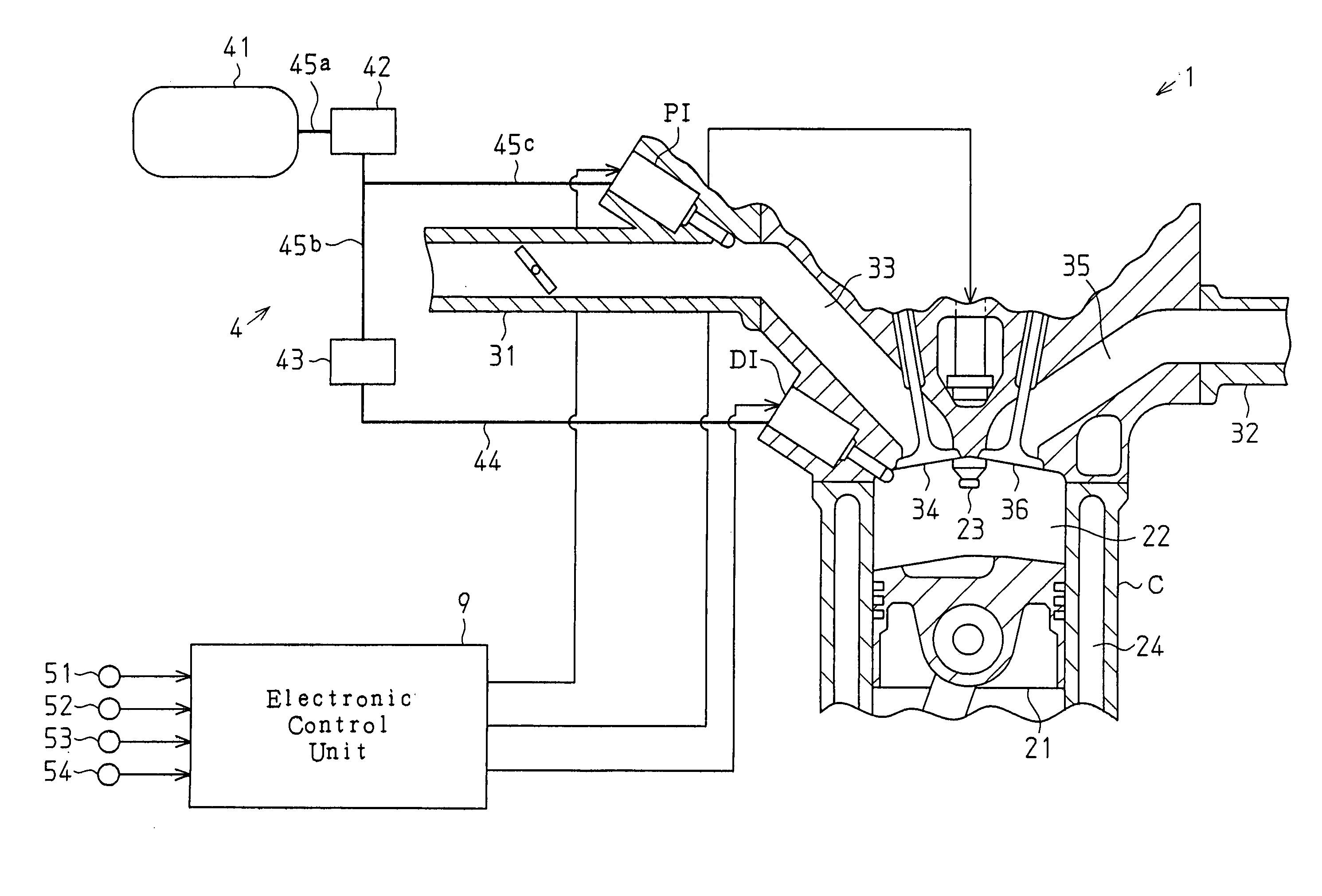
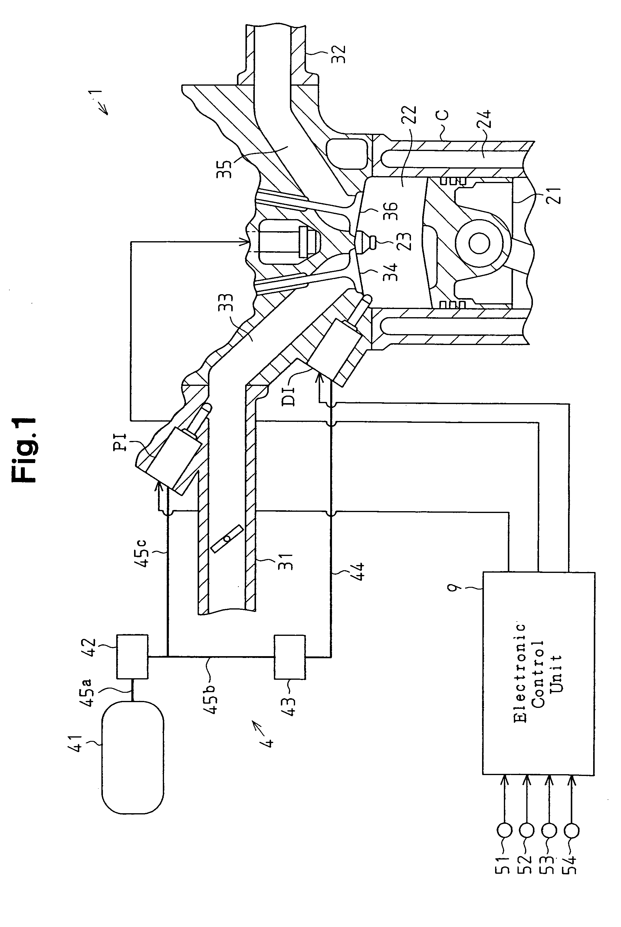
[0024]FIG. 1 schematically shows the structure of engine fuel and control systems in addition to the peripheral structure of an engine cylinder.

[0025] An engine 1 includes cylinders C. A direct injector DI is provided for each cylinder C for directly injecting fuel into the cylinder C. A piston 21 reciprocates in the cylinder C. A combustion chamber 22 is defined in the cylinder C between the top face of the piston 21 and the walls of the cylinder C.

[0026] The cylinder C is connected to an intake passage 31 and an exhaust passage 32. The intake passage 31 is provided with a port injector (intake injector) PI, which injects fuel into an intake port 33 of the cylinder C. The intake passage 31 is connected, to the combustion chamber 22 via the intake port 33. An intake valve 34 is arranged in the intake port 33 to open and close th...


PUM


Abstract

A fuel injection controller for an engine having a direct injector for injecting fuel into a cylinder and an intake injector for injecting fuel into an intake passage. When the engine is idling, the controller reduces a target engine speed while preventing the engine from stalling. The fuel injection controller supplies fuel to the engine through the direct injector and the intake injector when the engine is idling. The electronic control unit determines if there is a possibility of the engine stalling when the engine is idling. When having determined that there is such a possibility, the electronic control unit increases the fuel injection amount of the direct injector.

Description

BACKGROUND OF THE INVENTION [0001] The present invention relates to a fuel injection controller for use in an engine, having a direct injector for injecting fuel into a cylinder and an intake injector for injecting fuel into an intake passage, to control the drive mode of the injectors based on the operation condition of the engine. [0002] Such an engine is supplied with fuel in one of the next injection modes. [0003] (a) Fuel is supplied to the engine by only the direct injector (in-cylinder injector). [0004] (b) Fuel is supplied to the engine by only the intake injector. [0005] (c) Fuel is supplied to the engine by both the direct injector and the intake injector. [0006] The supply of fuel to the engine by both the direct injector and the intake injector when the engine is idling reduces the amount of fuel that is injected by the intake injector and deposited on the walls of the intake passage. This enables the target speed (the target engine speed during idling) to be lowered so ...

Claims


Application Information

Patent Timeline
Patent Type & Authority Applications(United States)
IPC IPC(8): F02M61/14F02D31/00F02D41/02F02D41/04F02D41/08F02D41/14F02D41/16F02D41/22F02D41/30F02D41/34F02D41/40F02D45/00F02M69/04
CPCF02D41/08F02D41/1498F02D41/16F02D41/0097F02D2041/389F02D31/003F02D41/3094
Inventor SHIBAGAKI, NOBUYUKI
Owner TOYOTA JIDOSHA KK
Why Eureka
Try Eureka