Fuel-efficient driving system

a driving system and fuel-efficient technology, applied in the direction of braking systems, electric control, instruments, etc., can solve the problems of difficult to reduce the speed to a requested vehicle, vehicle behavior becomes jerky, and the gradient at an actual traveling position is not necessarily constant, so as to achieve the effect of reducing the braking force, improving the fuel efficiency of the vehicle, and avoiding energy was

Active Publication Date: 2011-09-29
VOLVO LASTVAGNAR AB
View PDF4 Cites 4 Cited by
  • Summary
  • Abstract
  • Description
  • Claims
  • Application Information

AI Technical Summary

Benefits of technology

[0028]According to the present invention provided with the above-mentioned constructions, since the present invention is constructed to determine (calculate) the target speed (requested vehicle speed Vd) of the vehicle from the vehicle speed (Va) and the data of the descending slope (the distance L from the current position to the descending-slope starting point, the target vehicle speed Vt at the descending-slope starting point and the like), the target speed (Vd) at the spot where the vehicle (1) is traveling can be decreased linearly (claim 2), and the target speed (Vd) at the spot where the vehicle (1) is traveling can be decreased linearly (gradually) (claim 3), repetition of fuel-cut and fuel injection before the descending-slope starting point P2 can be suppressed.
[0029]That is, the fuel-cut or the fuel injection makes a vehicle behavior unstable (jerky) and gives a sense of unstableness or a sense of discomfort to a vehicle passenger, but since the repetition of fuel-cut and fuel injection is suppressed in the present invention, a sense of unstableness or a sense of discomfort is prevented from being given to the vehicle passenger.
[0030]Moreover, according to the present invention, since the target speed (Vd) at the spot where the vehicle (1) is traveling can be decreased linearly (gradually) (claim 3), a starting point (P1) where the vehicle traveling speed (Va) is decreased can be set at a position away from the descending-slope starting point (P2) as compared with the prior art.
[0031]That is, since the distance for which the vehicle (1) travels with a decreased speed (the distance L from the point P1 where deceleration is started to the descending-slope starting point P2) can be made longer than that in the prior art, deviation between the vehicle speed (Va) and the target speed (V) at the descending-slope starting point becomes smaller even in the case shown in FIG. 6, and a frequency of braking in the middle of the descending slope becomes fewer. Thus, energy is not wasted by braking and fuel efficiency of the vehicle is improved. Also, since the distance for which the vehicle can travel while being subjected to braking can be made shorter, the fuel-saving effect can be exerted further effectively.

Problems solved by technology

However, even if the map is to be improved precisely, the gradient at an actual traveling position is not necessarily constant.
Also, in the case of a cargo vehicle, its mass is greatly varied whether the vehicle is empty or loaded, and thus, deceleration is largely different at the fuel-cut between the empty vehicle and the loaded vehicle, and it has been difficult to reduce the speed to a requested vehicle speed (target vehicle speed) at start of the descending slope both in the empty vehicle and the loaded vehicle.
Because of such control, fuel might be injected immediately before entering the descending slope, and in that case, a vehicle behavior becomes jerky, and a driver would have a sense of discomfort, which is a problem.
At the same time, there is also a problem of a bad influence on the fuel efficiency.
As a result, a driving feeling before and after the descending-slope starting point P2 becomes jerky, and fuel efficiency is deteriorated by the temporary fuel injection.
However, similarly to the case shown in FIG. 6, the actual vehicle speed Va at the descending-slope starting point P2 exceeds the target vehicle speed Vt at entering the descending slope, and the frequency of operating the auxiliary brake in the middle of the descending slope is increased and thus, the problem of deterioration in fuel efficiency still remains.

Method used


Image

  • Fuel-efficient driving system
  • Fuel-efficient driving system
  • Fuel-efficient driving system

Examples


Embodiment Construction

[0039]An embodiment of the present invention will be described below by referring to the attached drawings.

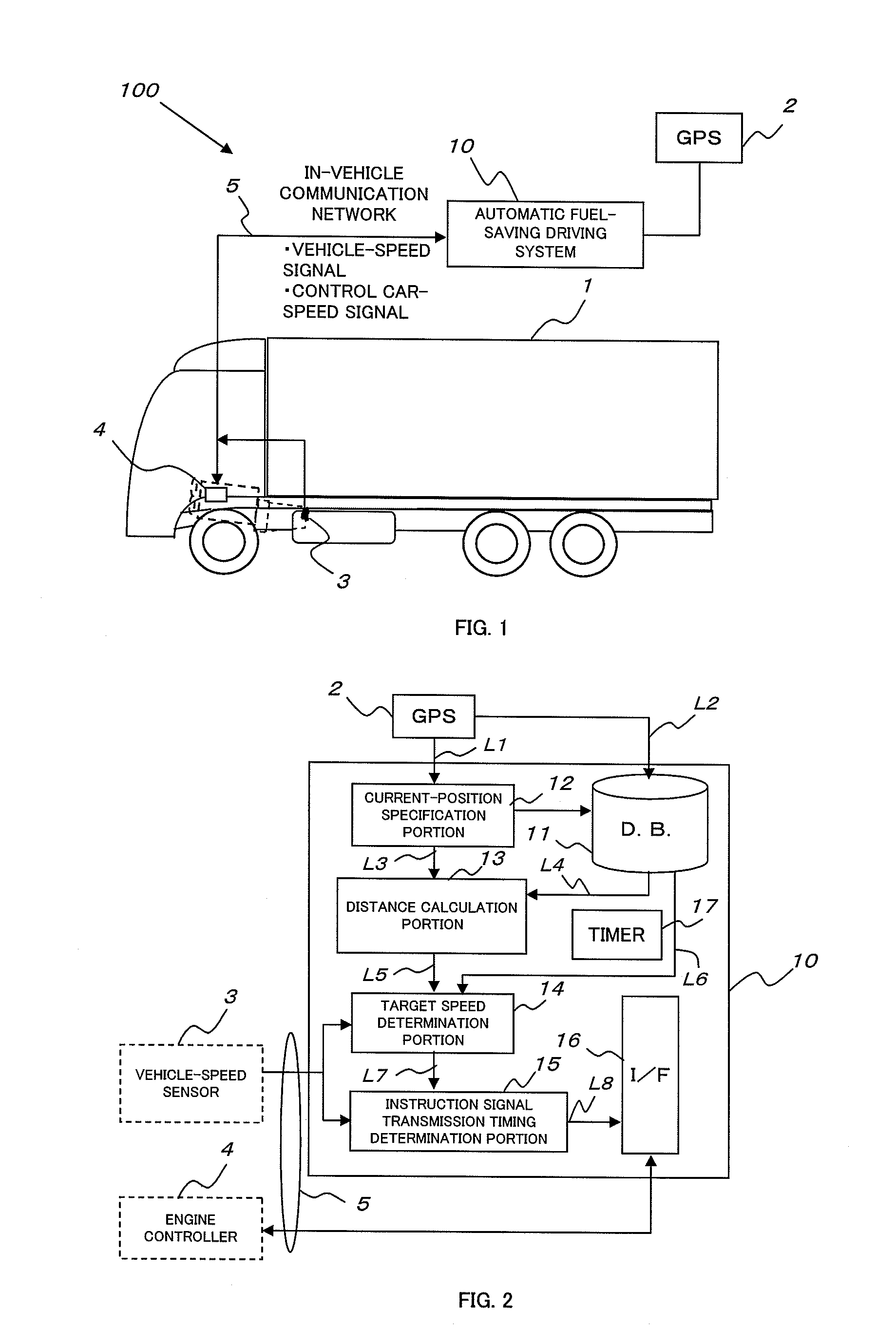
[0040]In FIG. 1, a fuel-saving driving system according to the embodiment of the present invention is indicated in entirety by reference numeral 100.

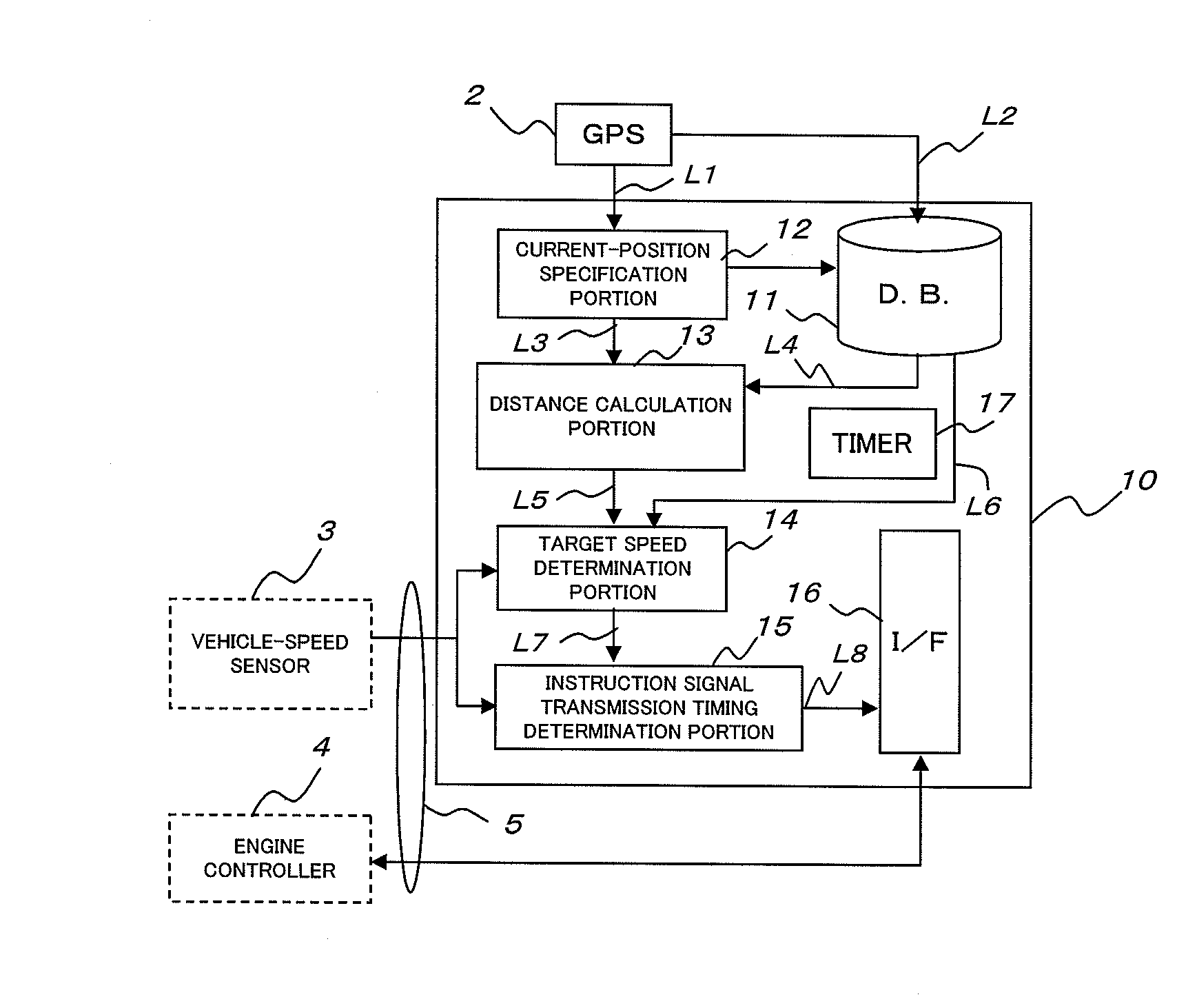
[0041]The fuel-saving driving system 100 has a vehicle 1, a GPS 2, which is a vehicle position specifying device, a vehicle speed sensor 3, an engine controller 4, an in-vehicle communication network 5, and a control unit 10, which is control means of the automatic fuel-saving driving system.

[0042]In this embodiment, the position of the vehicle is specified by using a Global Positioning System, and the GPS 2, which is a vehicle position specifying device, receives position information or the like from a satellite of the Global Positioning System.

[0043]The in-vehicle communication network 5 connects the control unit 10 to the vehicle speed sensor 3 and the engine controller 4.

[0044]FIG. 2 illustrates a construction of the control un...


PUM


Abstract

The present invention has an object to provide a fuel-saving driving system which gradually decreases a target vehicle speed from start of control to passage of a descending-slope starting point in a linear form and can obtain fuel-saving and smooth driving feeling without repeating fuel-cut and injection.
The present invention has a vehicle-position specifying device (2) for specifying the position of a vehicle, a storage device (11) for storing data of a descending slope located in the vehicle traveling direction, a vehicle speed measuring device (3) for measuring a speed (Va) of the vehicle (1), and a controller (10), the controller (10) has a function of determining (calculating) a target speed (requested speed Vd) of the vehicle (1) from the vehicle speed (Va) and the data of the descending slope.

Description

[0001]The present invention relates to an automatic control system for fuel-saving driving of an automobile and particularly to automatic control which can further reduce fuel consumption when driving changes to descending.BACKGROUND OF THE INVENTION[0002]As a prior art, a fuel-saving system that effectively promotes fuel-saving driving using road gradient information and a control method thereof are disclosed (See Patent Document 1, for example).[0003]In the prior art (Patent Document 1), improvement in fuel efficiency is promoted by using acceleration energy on a descending slope or in more detail by performing speed-reduction control before the descending slope.[0004]In the prior art (Patent Document 1), an advice position for fuel-cut before the descending slope (a position where an advice is given to a driver) or a control position for fuel-cut in an automatic fuel-saving driving system (a position where fuel is cut by automatic control) is determined by a vehicle speed (a car ...

Claims


Application Information

Patent Timeline
Patent Type & Authority Applications(United States)
IPC IPC(8): F02D41/30
CPCB60T7/12B60T7/18B60T2201/04B60W30/18009Y02T10/56B60W2550/402B60Y2200/14F02D41/045F02D41/123B60W2550/143B60W2552/20B60W2556/50Y02T10/40Y02T10/84
Inventor NISHIYAMA, YOSHITAKAKUBO, TOMOKI
Owner VOLVO LASTVAGNAR AB
Why Eureka
Try Eureka