Position and speed synchronization for a dual linear actuator flap system

a dual-linear actuator and actuator technology, applied in the field of aircraft flap systems, can solve the problems of undesirable bending of the flap panel, motor windings and/or power electronics drives, and the actuator positions are different, so as to reduce the target speed of the linear actuator(s), prevent or minimize the skew of the flap, and limit the output torque

Active Publication Date: 2016-01-28
EATON INTELLIGENT POWER LTD
View PDF1 Cites 6 Cited by
  • Summary
  • Abstract
  • Description
  • Claims
  • Application Information

AI Technical Summary

Benefits of technology

[0006]To prevent or minimize flap skew, two linear actuators may be synchronized in linear position during flap extension and / or retraction. Furthermore, due to high applied torques on one or both of the actuators, motor current limiting may be desirable in order to limit output torque and prevent the motor current from increasing beyond a threshold beyond which damage to the motor windings and / or the power electronics drive may result. Motor current limiting can be achieved by reducing the target speed of the linear actuator(s) with high applied torque(s), which may result in a position difference between the two linear actuators subject to synchronization / correction. If current limiting is applied to one or both of the motors, speed synchronization may be applied in addition to the position-based synchronization noted above.

Problems solved by technology

The dynamic variations of the load torque applied to each of the two actuators may potentially result in “force fighting” that can affect motor position and adjusted target speed of each actuator, possibly resulting in a difference in the positions of the actuators.
Such position differences can cause problems such as undesirable bending in the flap panel, i.e., flap skew.
Furthermore, due to high applied torques on one or both of the actuators, motor current limiting may be desirable in order to limit output torque and prevent the motor current from increasing beyond a threshold beyond which damage to the motor windings and / or the power electronics drive may result.
Motor current limiting can be achieved by reducing the target speed of the linear actuator(s) with high applied torque(s), which may result in a position difference between the two linear actuators subject to synchronization / correction.

Method used


Image

  • Position and speed synchronization for a dual linear actuator flap system
  • Position and speed synchronization for a dual linear actuator flap system
  • Position and speed synchronization for a dual linear actuator flap system

Examples


Embodiment Construction

[0014]Reference will now be made in detail to embodiments of the present invention, examples of which are described herein and illustrated in the accompanying drawings. While the invention will be described in conjunction with embodiments, it will be understood that they are not intended to limit the invention to these embodiments. On the contrary, the invention is intended to cover alternatives, modifications and equivalents, which may be included within the spirit and scope of the invention as defined by the appended claims.

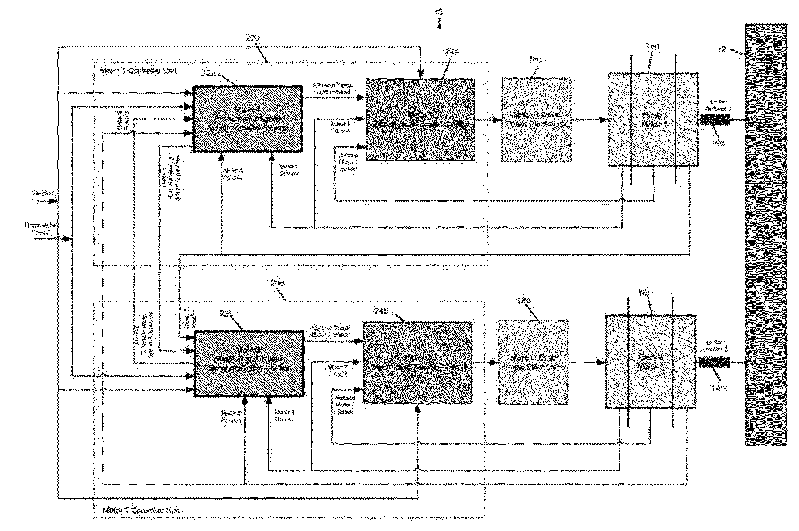
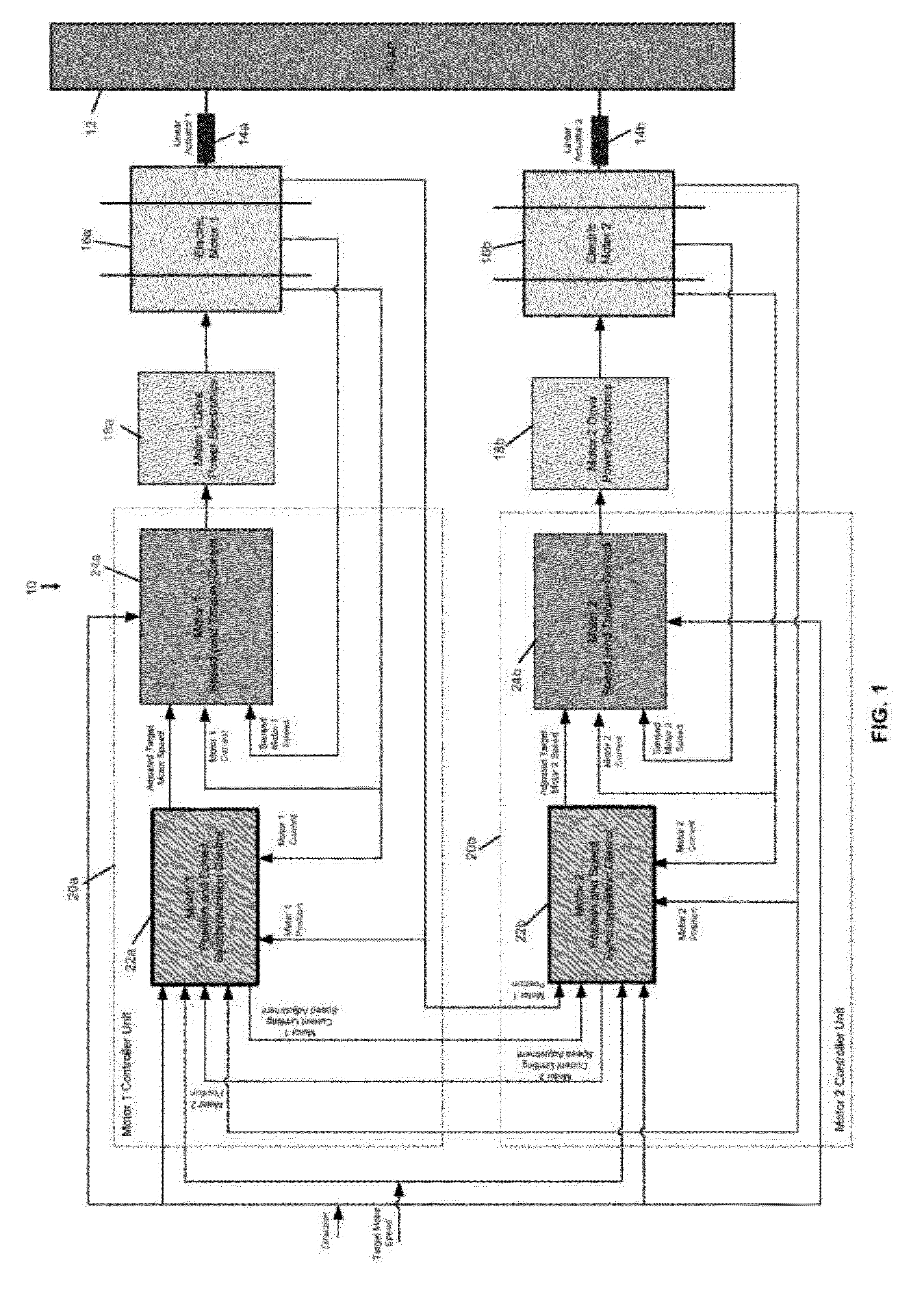
[0015]FIG. 1 is a block diagram view of an exemplary flap actuation system 10 including a flap 12 coupled to a first actuator 14a and a second actuator 14b. The first actuator 14a may be driven by a first electric motor 16a, and the second actuator 14b may be driven by a second electric motor 16b. Each electric motor 16a, 16b may be coupled with respective motor drive power electronics 18a, 18b, and each motor drive power electronics 18a, 18b may be coupled wit...


PUM


Abstract

A method for controlling a first motor and a second motor to synchronize respective positions of the first motor and the second motor may comprise comparing the positions to determine a position difference, incrementally increasing a speed of one of the first motor and the second motor and incrementally decreasing a speed of the other of the first motor and the second motor according to the position difference, and repeating the incrementally increasing and incrementally decreasing until the respective positions are synchronized. Additionally, motor current limiting may be applied by reducing the target speed of the motor(s) with high applied torque(s), which may result in a position difference between the two motors subject to synchronization/correction. If current limiting is applied to one or both of the motors, speed synchronization may be applied in addition to position-based synchronization.

Description

CROSS-REFERENCE TO RELATED APPLICATION[0001]This application is a national stage filing based upon International Application No. PCT / US2013 / 031720, with an international filing date of Mar. 14, 2013, the disclosure of which is incorporated herein by reference in its entirety.BACKGROUND[0002]1. Technical Field[0003]The present disclosure relates generally to aircraft flap systems, including synchronization of flap actuators.[0004]2. Description of the Related Art[0005]In aircraft flap systems, multiple actuators may be involved in controlling the extension and retraction of one or more flap panels. For example, a single flap panel may be actuated by two actuators. The dynamic variations of the load torque applied to each of the two actuators may potentially result in “force fighting” that can affect motor position and adjusted target speed of each actuator, possibly resulting in a difference in the positions of the actuators. Such position differences can cause problems such as undes...

Claims


Application Information

Patent Timeline
Patent Type & Authority Applications(United States)
IPC IPC(8): H02P5/68B64C9/16
CPCB64C9/16H02P5/68H02P5/54H02P5/56
Inventor FATTAL, SOUREN, GEORGES
Owner EATON INTELLIGENT POWER LTD
Why Eureka
Try Eureka