Self-propelling cleaner

a cleaner and self-propelling technology, applied in the field of self-propelling cleaners, can solve the problems of clogging the dust filter, complex configuration of the dust full detection unit, and frequency of the sound picked by the microphon

Inactive Publication Date: 2005-08-25
FUNAI ELECTRIC CO LTD
View PDF0 Cites 144 Cited by
  • Summary
  • Abstract
  • Description
  • Claims
  • Application Information

AI Technical Summary

Benefits of technology

[0010] In the self-propelling cleaner disclosed in JP-A-2002-360480, connection between the dust chamber 5 and the nozzle 4 with predetermined shape is made by the dust transporting pipe 6 with a cross-sectional area smaller than that of these nozzle 4 and dust chamber 5, and dust taken in the nozzle 4 by the brush 40 is led into the dust chamber 5 through the dust transporting pipe 6 by a drawing pressure of the discharge fan 13. As a result of this, the dust transporting pipe 6 may be clogged with dust such as a piece of paper with a predetermined size or larger. In this case, in the conventional self-propelling cleaner, dust clogging is detected by dust clogging detection mea...

Problems solved by technology

In the self-propelling cleaner described in JP-A-7-039498 thus, the frequency of the sound picked by the microphone must be detected once and a configuration of dust full detection unit becomes complicated.
As a result of this, the dust transporting pipe 6 may be clogged with dust such as a piece of paper with a predet...

Method used


Image

  • Self-propelling cleaner
  • Self-propelling cleaner
  • Self-propelling cleaner

Examples


first embodiment

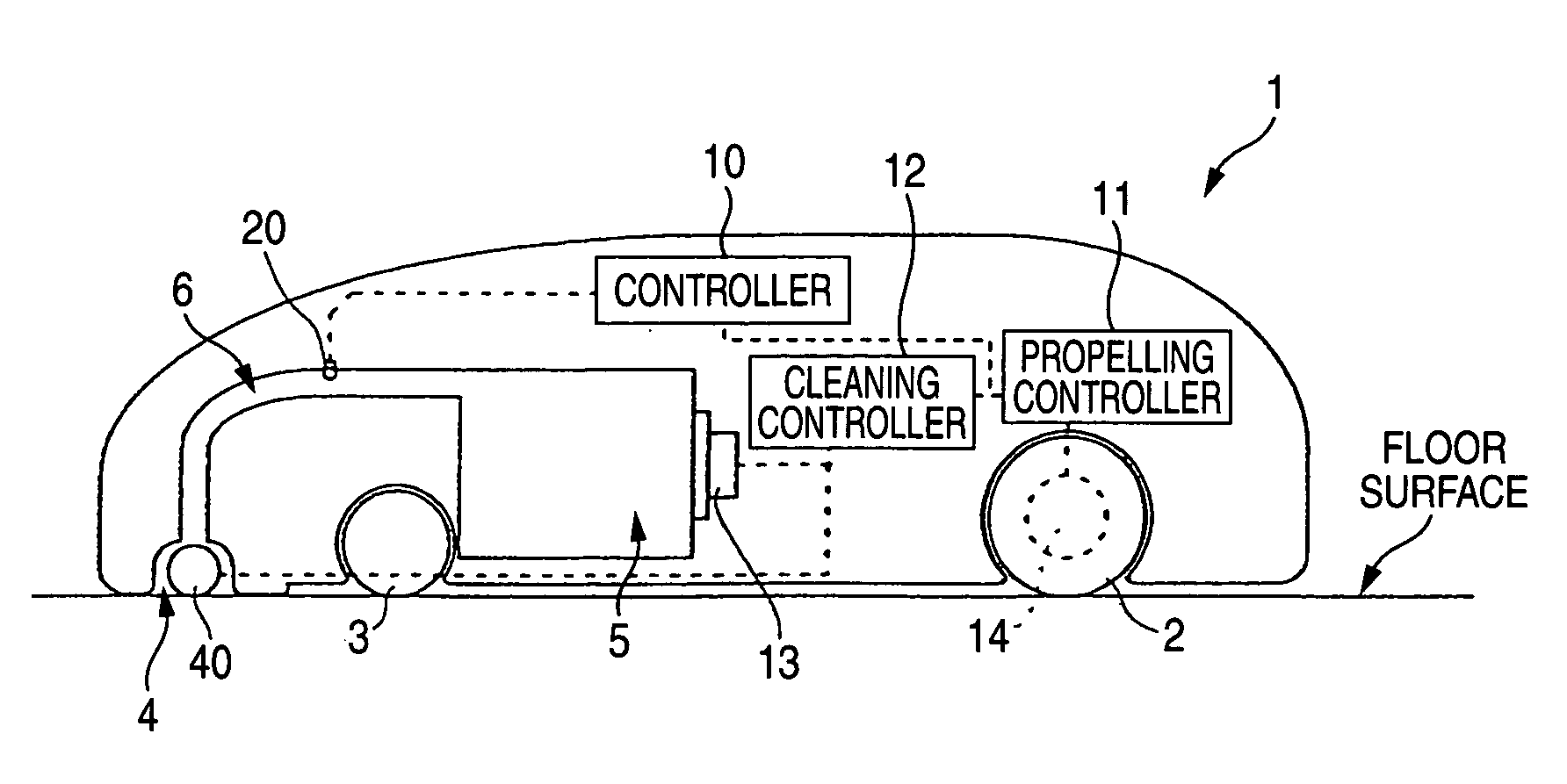
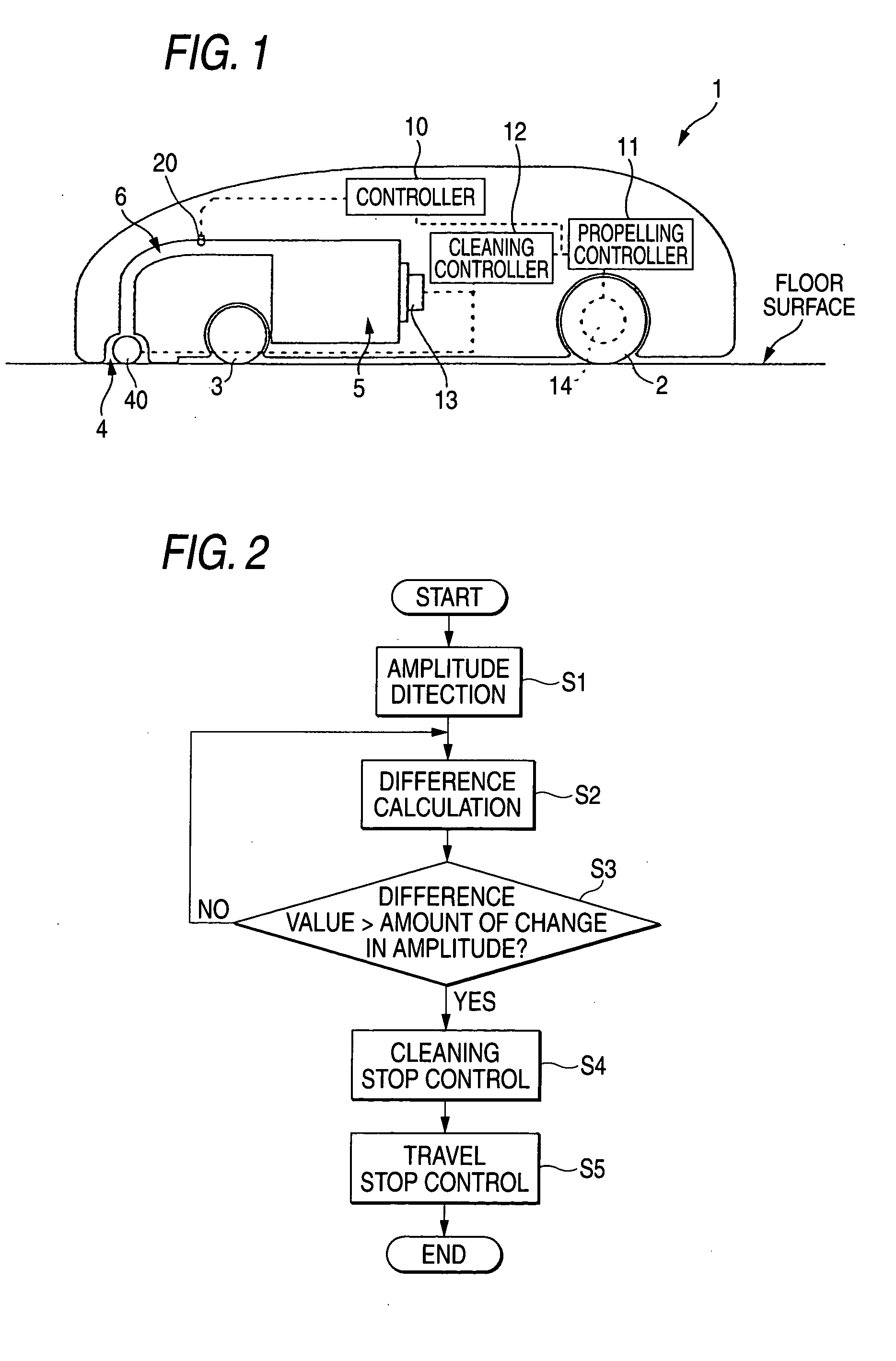
[0024]FIG. 1 is a configuration diagram showing a schematic configuration of a self-propelling cleaner according to a

[0025] The self-propelling cleaner includes propelling unit for moving a main body 1 along a preset track within a cleaning region, and cleaning unit for removing dust from a floor surface within the cleaning region and receiving the dust.

[0026] The right and left of a backward lower portion of the main body 1 are provided with drive wheels 2 and a driving motor 14 which is connected to each of the drive wheels 2 and rotates the drive wheels 2, and a forward lower portion of the main body 1 is provided with a driven wheel 3. Also, the driving motor 14 is electrically connected to a propelling controller 11 for controlling travel of the main body 1. These propelling controller 11, drive wheels 2, driving motor 14 and driven wheel 3 correspond to “propelling unit” of the invention.

[0027] Also, the main body 1 is provided with a nozzle 4 which is provided in a forward ...

second embodiment

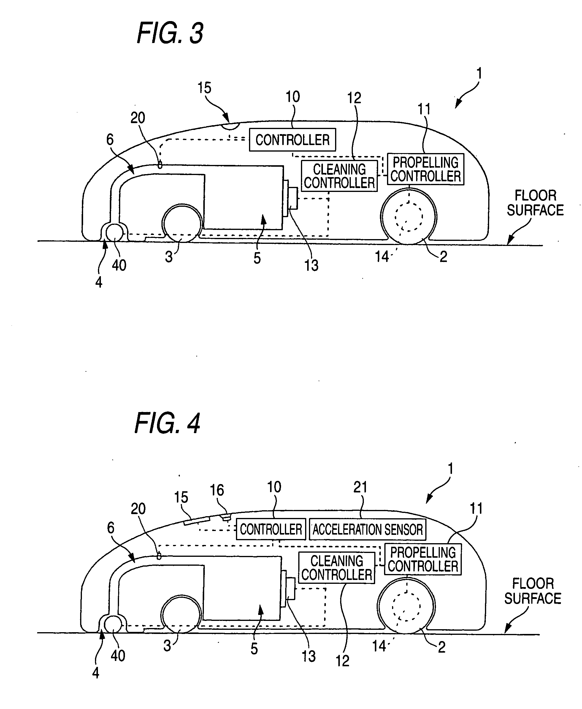
[0043] Next, a self-propelling cleaner will be described with reference to FIG. 3.

[0044]FIG. 3 is a block diagram showing a schematic configuration of a self-propelling cleaner according to the second embodiment.

[0045] The self-propelling cleaner shown in FIG. 3 includes a display part 15 in the upper side of a main body 1, and other configurations are equal to those of the self-propelling cleaner shown in FIG. 1.

[0046] The display part 15 includes, for example, plural LED lamps, and notifies the outside of an operation state etc. of the main body 1 by changing luminous colors and luminous patterns. Luminous control of the display part 15 is performed by a controller 10, and the controller 10 outputs each control command to a propelling controller 11 and a cleaning controller 12 and also outputs a luminous control command according to the control command to the display part 15.

[0047] In such a self-propelling cleaner, as described above, when sound volume picked by a microphone ...

third embodiment

[0050] In the self-propelling cleaner an acceleration sensor 21 corresponding to “speed detection unit” of the invention is fixed and installed in the main body 1, and the acceleration sensor 21 always observes acceleration of the main body 1 and outputs the acceleration to the controller 10. Thus, the controller 10 can always calculate a speed, a moving distance and a direction of the main body 1 by always observing the acceleration of the main body 1 by the acceleration sensor 21.

[0051] Initial amplitude according to sound volume of the inside of the dust transporting pipe 6 in the case of sucking dust in a state in which dust is not deposited inside the dust chamber 5 at all and the amount of change in amplitude indicating what amount amplitude changes with respect to the initial amplitude in the case of sucking dust in a state in which the nozzle 4 or the dust transporting pipe 6 is clogged with dust are previously stored in the controller 10. Then, the controller 10 computes a...


PUM


Abstract

In a dust transporting pipe 6, a microphone 20 is installed in a predetermined position. An output signal of the microphone 20, that is, a voltage signal of amplitude according to sound volume of the inside of the dust transporting pipe 6 picked is inputted to a controller 10. Initial amplitude according to sound volume of the inside of the dust transporting pipe 6 in the case of sucking dust in a state in which there is no dust inside a dust chamber 5 at all and the amount of change in amplitude indicating what amount amplitude changes from the initial amplitude in the case that the dust chamber 5 becomes full of dust are previously stored in the controller 10.

Description

BACKGROUND OF THE INVENTION [0001] 1. Field of the Invention [0002] This invention relates to a self-propelling cleaner for cleaning while automatically moving within a preset region. [0003] 2. Description of the Related Art [0004] A self-propelling cleaner includes a propelling unit for propelling a main body and a cleaning unit for doing cleaning, and does cleaning while automatically moving within a preset region. When dust accommodated in a dust chamber is in a full state, dust cannot be sucked surely and the primary purpose of the cleaner for doing cleaning cannot be achieved. As a result of this, a method for detecting the full of dust of the dust chamber has been devised conventionally. [0005] For example, a method for detecting the full of dust of a dust chamber of a self-propelling cleaner includes a method in which a frequency of sound of the inside of a pipe for leading dust to a dust chamber is measured and when this frequency reaches a predetermined value, it is detecte...

Claims


Application Information

Patent Timeline
IPC IPC(8): A47L5/00A47L9/19A47L9/28
CPCA47L9/19A47L9/2805A47L2201/00A47L9/2857A47L9/2889A47L9/2852
Inventor UEHIGASHI, NAOYA
Owner FUNAI ELECTRIC CO LTD
Why Eureka
Try Eureka