Archery bow sight

Inactive Publication Date: 2005-08-25
BEM
View PDF20 Cites 20 Cited by
  • Summary
  • Abstract
  • Description
  • Claims
  • Application Information

AI Technical Summary

Benefits of technology

[0012] Activation of the LED causes illumination of a plurality of fiber optic elements. Each of the fiber optic elements has a first end which is secured to one of the pin heads of one of the sight pins. Similarly, each of the fiber optic elements has a second end which is located proximate the LED in a conduit in the main body of the bow sight. This conduit in the main body of the bow sight extends between the battery receptacle and the circular passageway of the main body. Each of the sight pins of the bow sight is equipped with a fiber optic element of a different color so that the archer may easily distinguish between sight pins, even in

Problems solved by technology

One difficulty with such archery bow sights is that the sight pins are commonly horizontally mounted in a manner shown in U.S. Pat. Nos. 6,000,141; 6,508,005; and 5,231,765.
Sight pins mounted in this horizontal manner may obstruct the view of the archer and therefore adversely affect his or her shooting accuracy.
Another difficulty with known bow sights is that during low light conditions, such as early morning or late evening, the archer may have difficulty selecting the correct sight pin to use to aim at the target.
One difficulty with such a complicated system is that

Method used


Image

  • Archery bow sight
  • Archery bow sight
  • Archery bow sight

Examples


Embodiment Construction

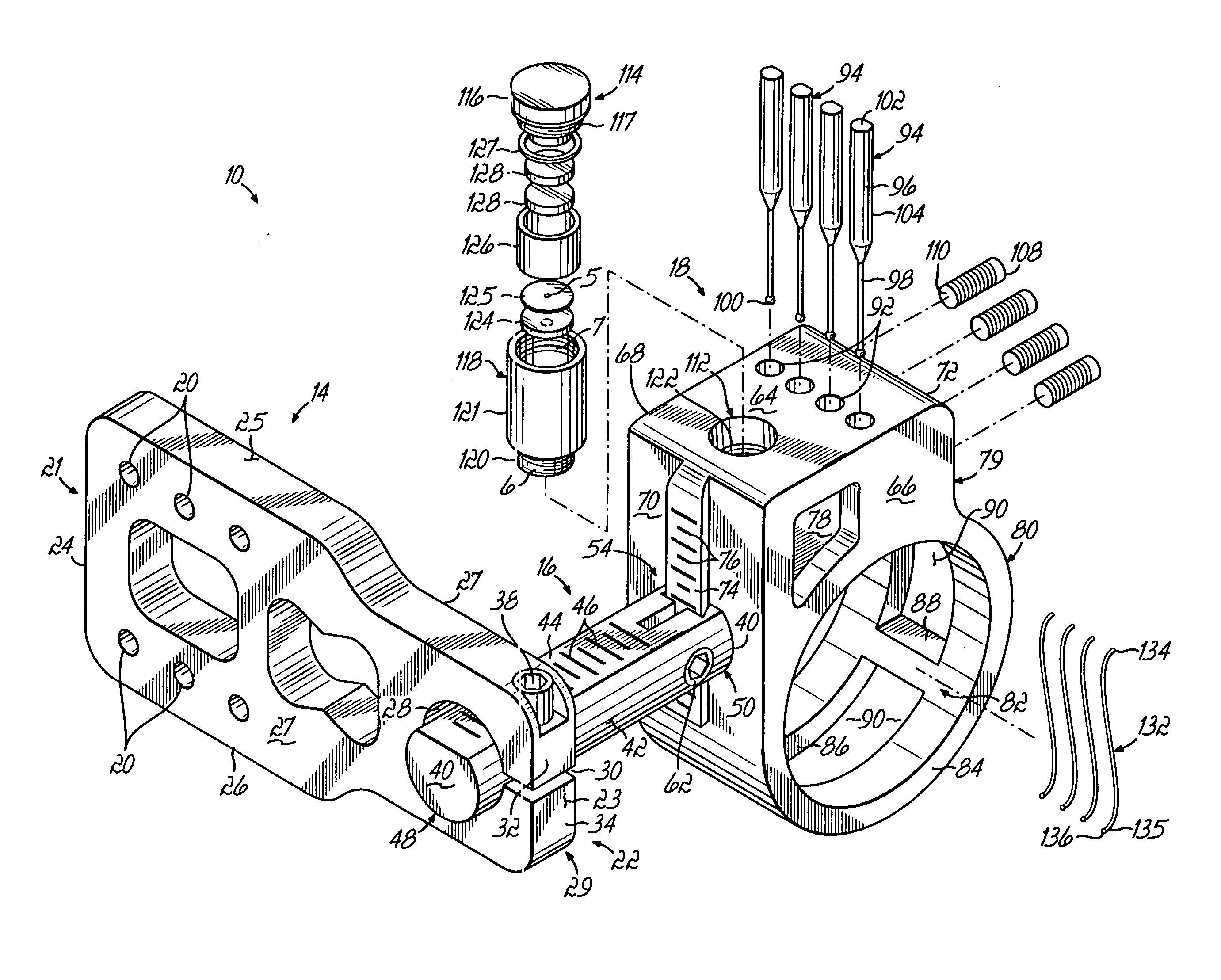
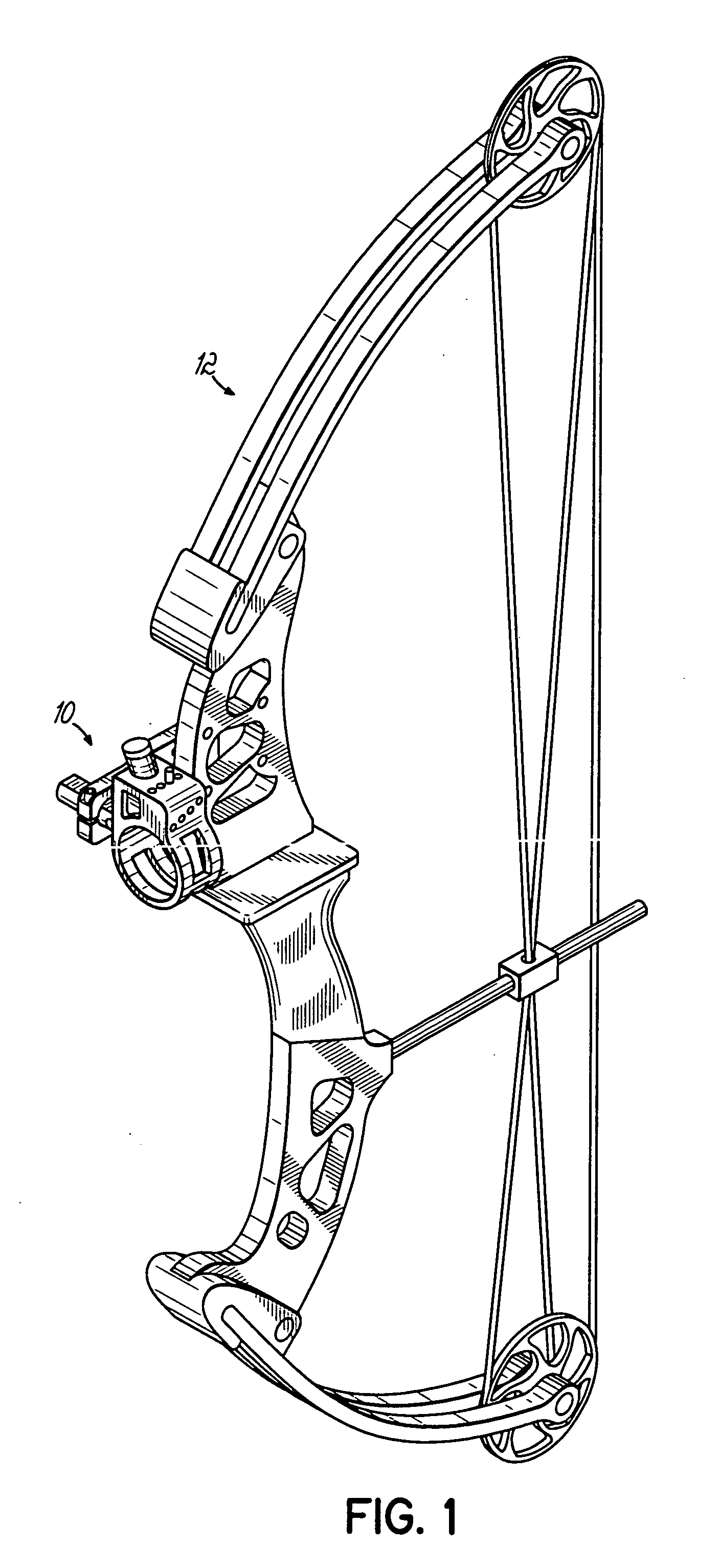
[0021] Referring to the drawings and particularly to FIG. 1, there is illustrated a bow sight 10 for use on a bow 12. The bow 12 is not intended to form part of the present invention; the bow sight 10 of the present invention may be used on any bow.

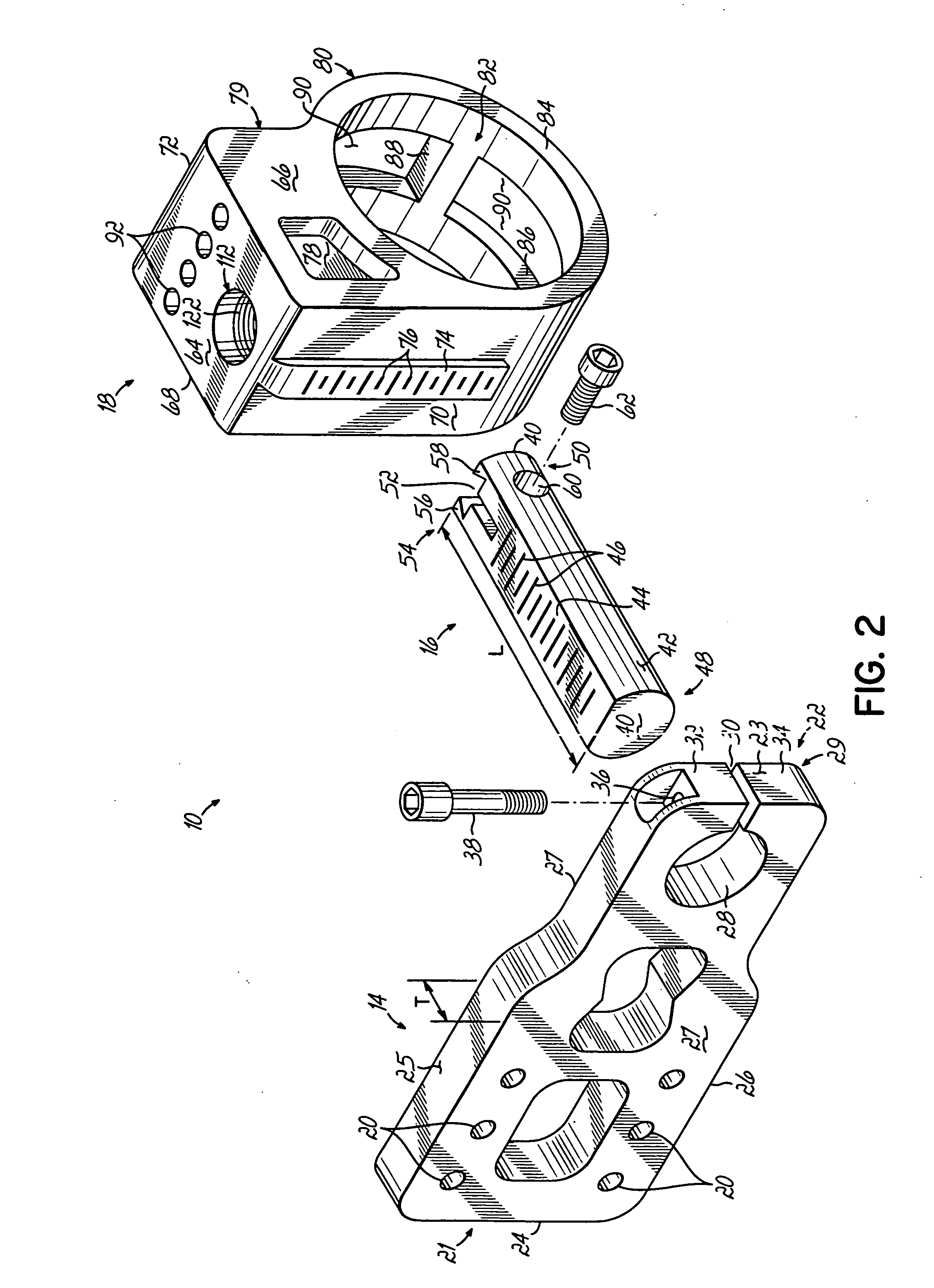
[0022] Referring to FIG. 2, the bow sight 10 of the present invention has three principal components: a mounting bracket 14, an adjustment bar 16 and a main body 18. As is conventional, the mounting bracket 14 is secured to the bow 10 with fasteners (not shown) which pass through openings 20 in the mounting bracket 14.

[0023] Each of these principal components, the mounting bracket 14, adjustment bar 16 and main body 18 is preferably made of anodized aluminum, but may be made with any other suitable material.

[0024] The mounting bracket 14 has a first or rear end 21 and a second or front end 22. Similarly, the mounting bracket 14 has a front surface 23, a rear surface 24, a top surface 25, a bottom surface 26 and a pair of side surfaces ...


PUM


Abstract

An electronically lighted bow sight is provided which may be attached to conventional bows. The bow sight includes a main body having a circular passageway in which are located multiple sight pins. The main body may be adjusted vertically and horizontally. The ends of the sight pins are illuminated by an archer turning a knob at the top of the main body of the bow sight. A battery powered LED illuminates a plurality of fiber optic elements extending down to the ends of the sight pins. The fiber optic elements are different colors to help the archer distinguish the sight pins.

Description

FIELD OF THE INVENTION [0001] This invention relates generally to the field of archery and more particularly to an archery bow sight having sight or aiming pins. BACKGROUND OF THE INVENTION [0002] Archery bow sights utilizing a plurality of sight pins have been known in the art for many years. Typically, these sights utilize a bracket or other mounting structure for mounting the sight to a bow and a plurality of sight pins secured to structure such as a pin plate. The sight pins have aligned ends visible to the archer. The sight is mounted to the bow in a manner so that when the bow is drawn, the archer can look through a peep sight provided in the bow cable and align the tip or end of one of the sight pins attached to the sight with the target. For sights utilizing a plurality of sight pins having their tips vertically aligned, each individual sight pin is typically provided for aiming the bow at a target at a particular distance from the archer. For example, one pin may be positio...

Claims


Application Information

Patent Timeline
IPC IPC(8): F41G1/467
CPCF41G1/467
Inventor MEADOWS, TIMOTHY D.
Owner BEM
Why Eureka
Try Eureka