
Pedal module

Active Publication Date: 2005-08-25
DENSO CORP
View PDF13 Cites 8 Cited by
  • Summary
  • Abstract
  • Description
  • Claims
  • Application Information

AI Technical Summary

Benefits of technology

[0006] An object of the invention is to provide a pedal module for preventing the occurrence of abnormal noises and the deterioration of feeling of depressing a pedal.

Problems solved by technology

Impact caused at this time produces abnormal noises and propagates to the pedal to impair feeling of depressing the pedal.

Method used


Image

  • Pedal module
  • Pedal module
  • Pedal module

Examples


first embodiment

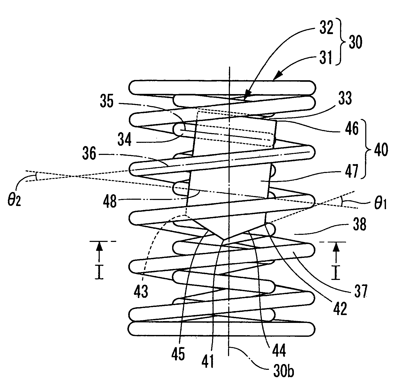
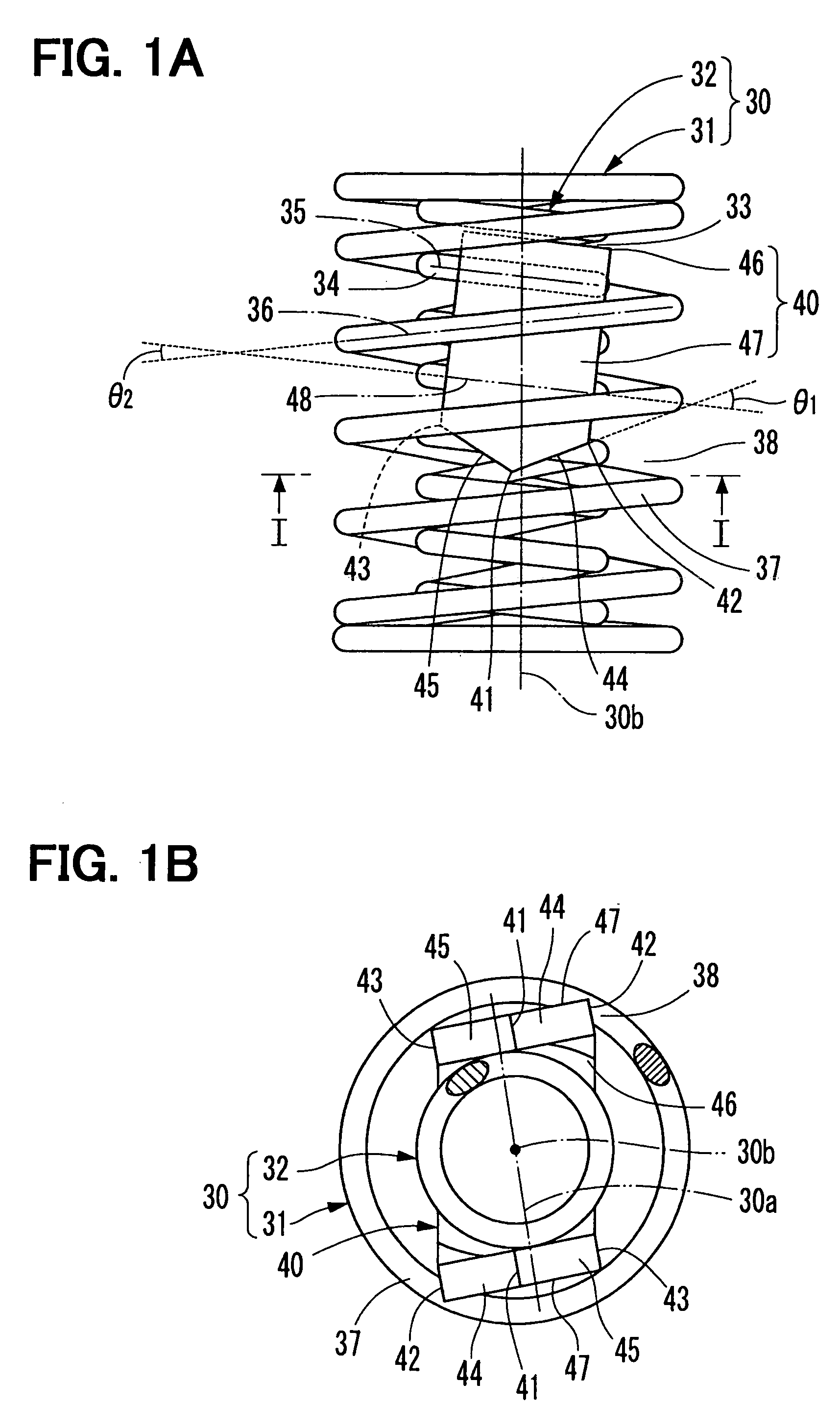
[0057] described above, it is possible to prevent the side end portions 42 in the direction of width of the respective inserting portions 47 from abutting against the outside coil 31 in the gap 38 between the windings and further to prevent the side end portions 42 from detaching from the outside coil after abutting to cause impact. Hence, it is possible to prevent the occurrence of abnormal noises and the deterioration of feeling of depressing the accelerator pedal as in the case of the conventional accelerator pedal.

[0058] Further, according to the first embodiment, because two inserting portions 47 are inserted between the outside coil 31 and the inside coil 32, it is possible to prevent the occurrence of abnormal noises and the deterioration of feeling of depressing the accelerator pedal and at the same time to improve an effect of preventing resonance with external vibration. In addition, since the damping part 40 having two inserting portions 47 like this is formed of a singl...

second embodiment

[0059] the present invention is a modification of the first embodiment and FIG. 5 shows a state where a damping part 50 in accordance with the second embodiment is detached from the double coil spring 30. Slant surface portions 51, 52, each of which connects the middle portion 41 in the direction of width to the side end portions 42, 43 in the both side end portions in the direction of length of the damping part 50, are formed respectively in the shape of a curved surface protruding toward the outer periphery. Also the damping part 50 like this can be bent in the shape of a letter U as is the case with the first embodiment and can be attached to the double coil spring 30 to produce the same operation as in the first embodiment. Hence, it is possible to prevent the occurrence of abnormal noises and the deterioration of feeling of depressing the accelerator pedal.

[0060] The third embodiment of the invention is a modification of the first embodiment and FIG. 6 shows a state where a dam...


PUM


Abstract

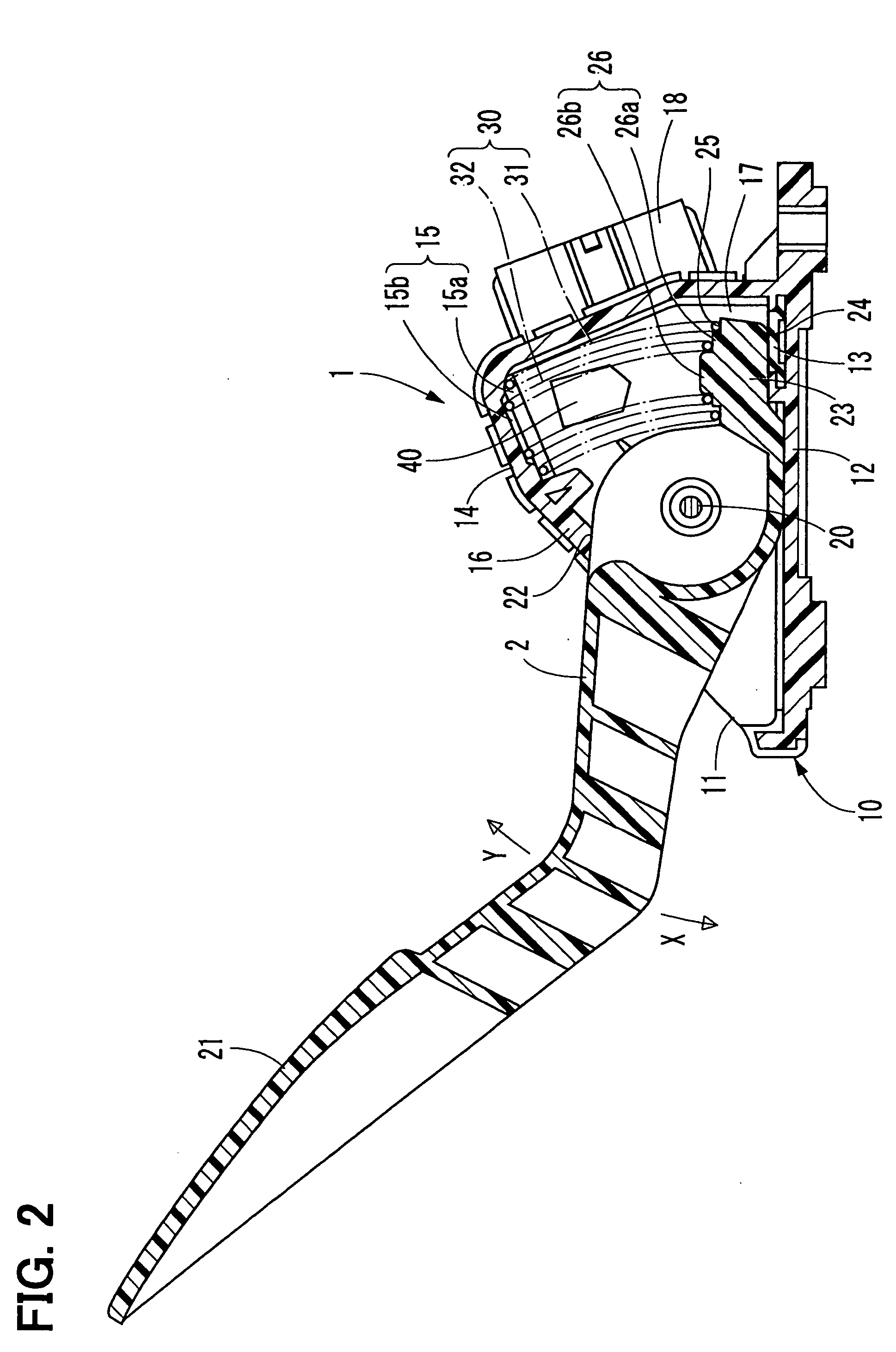
A pedal module includes a double coil spring, a pedal, and a damping part. The double coil spring includes an outside coil and an inside coil. The pedal turns in a forward direction when a depressing force is applied thereto and turns in a reverse direction when a restoring force of the double coil spring is applied thereto. The damping part has an inserting portion disposed between the outside coil and the inside coil. The inserting portion includes a middle portion and a first side end portion disposed relative to each other in a width direction that corresponds to a circumferential direction of the double coil spring. The middle portion crosses a radial axis of the double coil spring and protrudes beyond the first side end portion toward an axial end of the double coil spring.

Description

CROSS REFERENCE TO RELATED APPLICATIONS [0001] This application is based upon and claims the benefit of priority of Japanese Patent Application No. 2004-44460, filed on Feb. 20, 2004, the contents of which are incorporated herein by reference. FIELD OF THE INVENTION [0002] The present invention relates to a pedal module and, in particular, to a pedal module suitable for an accelerator for a vehicle. BACKGROUND OF THE INVENTION [0003] In a conventional pedal module used for an accelerator for a vehicle, a pedal is turned forward by the action of a depressing force and is reversed by the urging force of a spring. Among the modules like this is a publicly known module that reverses the pedal from a forward position by the use of a double coil spring, as disclosed in Japanese patent document JP-A No. 2003-39970. [0004] In recent years, it is thought that a damping part 100 as shown in FIG. 16 is arranged in the pedal module using a double coil spring. To be specific, the damping part 10...

Claims


Application Information

Patent Timeline
IPC IPC(8): B60K26/02F16F3/06G05G1/30G05G5/03H02K9/00
CPCG05G1/30Y10T74/20534Y10T74/20528G05G5/03
Inventor MAKINO, MASAHIROHASEGAWA, SHIGERUSAITO, TAKEHIRO
Owner DENSO CORP
Learn More