
Electronic device provided with rack and pinion

a technology of electronic devices and gears, applied in the direction of gearing, hoisting equipment, instruments, etc., can solve the problems of related art racks having such problems, and achieve the effect of preventing the occurrence of backlash and gear meshing noise, and simplifying construction

Inactive Publication Date: 2005-03-03
ORION ELECTRIC CO LTD
View PDF13 Cites 4 Cited by
  • Summary
  • Abstract
  • Description
  • Claims
  • Application Information

AI Technical Summary

Benefits of technology

[0012] Thus, a related art rack has such problems as mentioned above. What the present invention aims to solve these problems. An object of the present invention is to provide an electronic device provided with a rack and a pinion, having a simpler construction, capable of reliably preventing the occurrence of a backlash and meshing noise of gears, and not encountering a delay of a movement of a rack made by the rotation of a pinion.
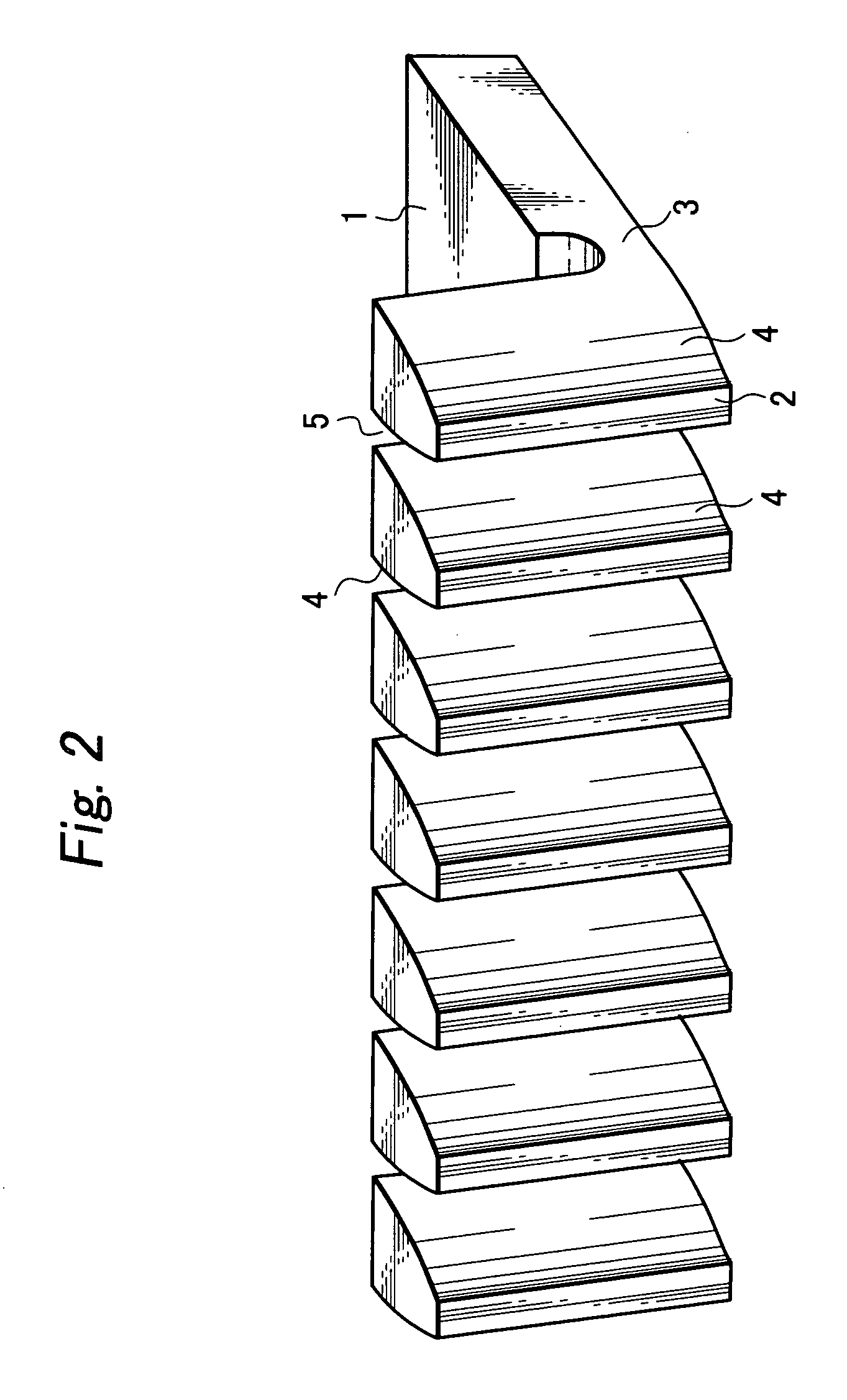
[0014] The rack may be molded integrally out of a synthetic resin, so that a rack having a suitable flexibility can be manufactured at a low cost. The teeth of the rack may be stood up via hinge portion respectively and arranged at predetermined intervals, so that the flexure of the teeth of the rack in the standing direction thereof occurs owing to the torsion or bend of the hinge portion. When the thickness of the hinge portion is set smaller than that of the base portion, the torsion or bend of the hinge portion occurs reliably.

Problems solved by technology

Thus, a related art rack has such problems as mentioned above.

Method used


Image

  • Electronic device provided with rack and pinion
  • Electronic device provided with rack and pinion
  • Electronic device provided with rack and pinion

Examples


Embodiment Construction

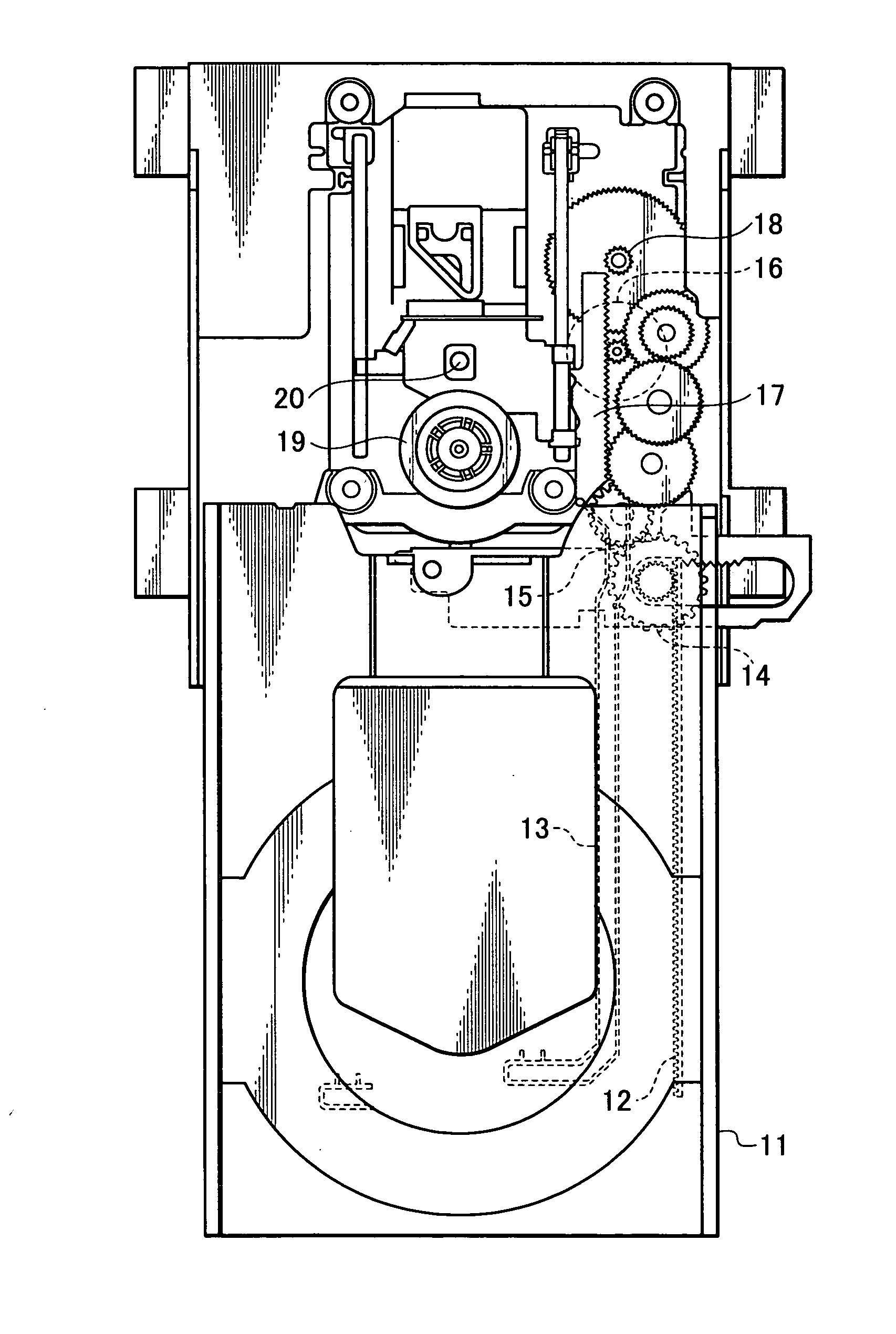
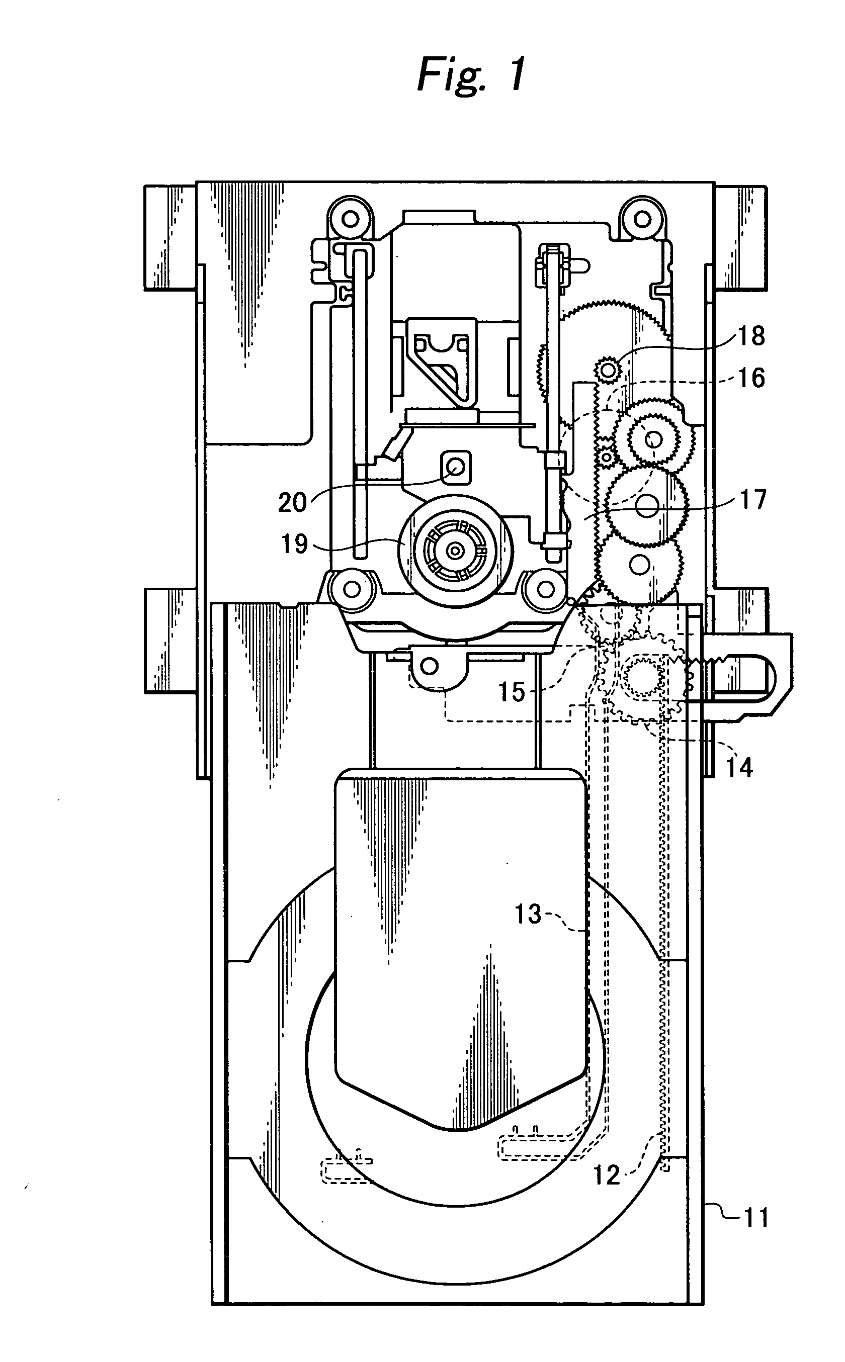
[0022] An embodiment of the present invention will now be described in detail with reference to the accompanying drawings. FIG. 1 shows a pickup-carrying disk device in an embodiment of the present invention in an opened state with a tray 11 drawn out. The tray 11 is provided in an upper surface thereof with a circular, shallow recess, in which a disk is fitted and set. A rack 12 is provided extending in the longitudinal direction on the side of a lower surface of the tray, and a substantially L-shaped guide groove 13 is provided along the rack 12. A pinion 14 is meshed with the rack 12, and a cam rod boss 15 is loosely fitted in the guide groove 13.

[0023] The pinion 14 is driven to rotate by a motor 16, and the rack 12 and tray 11 are moved back and carried into the interior of the disk device owing to the rotation of the pinion 14. The tray 11 is formed so that the tray 11 can be opened and closed by being moved forward and backward by a predetermined distance.

[0024] In the disk...


PUM


Abstract

To provide an electronic device having a rack and a pinion which reliably eliminates a backlash, and which is free from the occurrence of a delay of an operation during the rotation of the pinion, the rack is made of an elongated plate type base portion, and a plurality of teeth stood up in an inclined state at one side section of the base portion with a uniform pitch and formed integrally out of a flexible material. The teeth of the pinion are formed vertically so that the inclined teeth of the rack stand up substantially vertically and bend rearward when the teeth of the pinion are meshed with those of the rack.

Description

BACKGROUND OF THE INVENTION [0001] 1. Field of the Invention [0002] The present invention relates to a reciprocatingly sliding feed unit for various kinds of electronic devices, toys, timepieces and other kinds of precision machines, and more particularly to an electronic device provided with a rack and a pinion constituting such a feed unit as mentioned above. [0003] 2. Related Art [0004] In a reciprocatingly sliding feed unit uses in many cases a mechanism formed so that a rack and a pinion are meshed with each other. For example, in a disk device, a rack-pinion mechanism is used as a mechanism for withdrawing and inserting a tray from and into the disk device. In a traverse unit provided with a turntable on which a disk is mounted, an optical pickup is fixed thereto. The optical pickup has to be moved at a predetermined speed in accordance with a rotation of the disk, and a speedy and accurate movement of the optical pickup to a predetermined data position is demanded. A rack-pin...

Claims


Application Information

Patent Timeline
IPC IPC(8): F16H55/28F16H19/04G11B17/04G11B17/056G11B21/02
CPCG11B17/056
Inventor MINOWA, TAIZOHARADA, TOMOYUKI
Owner ORION ELECTRIC CO LTD
Learn More