Dual mode pneumatic fastener actuation mechanism

Inactive Publication Date: 2005-08-25
BLACK & DECKER INC
View PDF99 Cites 33 Cited by
  • Summary
  • Abstract
  • Description
  • Claims
  • Application Information

AI Technical Summary

Benefits of technology

[0010] In a further aspect, a depth adjustment system is included to permit varying the depth to which a fastener to be secured will be driven. In this aspect of the invention, a threaded thumb wheel is included to engage with a threaded portion of a pivot pin included on the intermediate linkage. A washer, biased into enga

Problems solved by technology

Typically, devices attempting to provide this dual actuation capability are structurally complex and require numerous components to achieve this functionality.
Furthermore, mechanisms for providing this dual actuation capability may be difficult to assemble thereby raising manufacturing costs and increasing the difficulty of repairing the device.
Typica

Method used


Image

  • Dual mode pneumatic fastener actuation mechanism
  • Dual mode pneumatic fastener actuation mechanism
  • Dual mode pneumatic fastener actuation mechanism

Examples


Embodiment Construction

[0033] Reference will now be made in detail to the presently preferred embodiments of the invention, examples of which are illustrated in the accompanying drawings.

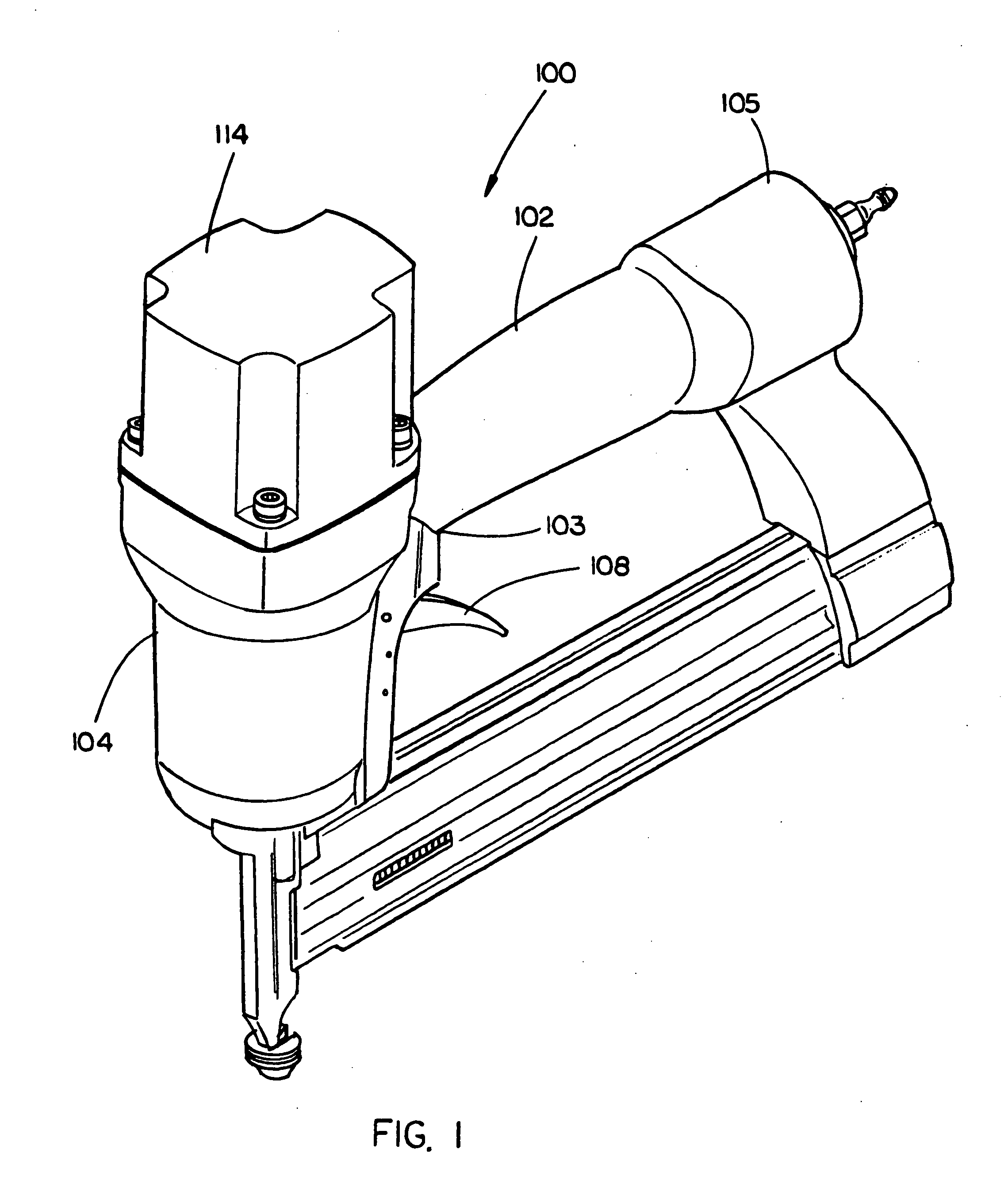
[0034] Referring now to FIG. 1, an exemplary embodiment of a pneumatic fastener 100 in accordance with the present invention is provided. In the exemplary embodiment, the pneumatic fastener 100 includes a handle 102 having a first end 103 and a second end 105. In the present embodiment, a housing 104 is coupled with the first end 103 of the handle 102. The handle 102 further includes a handle adapter 156, which enables the coupling of a compressed air supply to the pneumatic fastener 100. In addition, a trigger assembly 108 for controlling the firing of the pneumatic fastener 100 may be coupled with the handle 102, proximal to the first end 103.

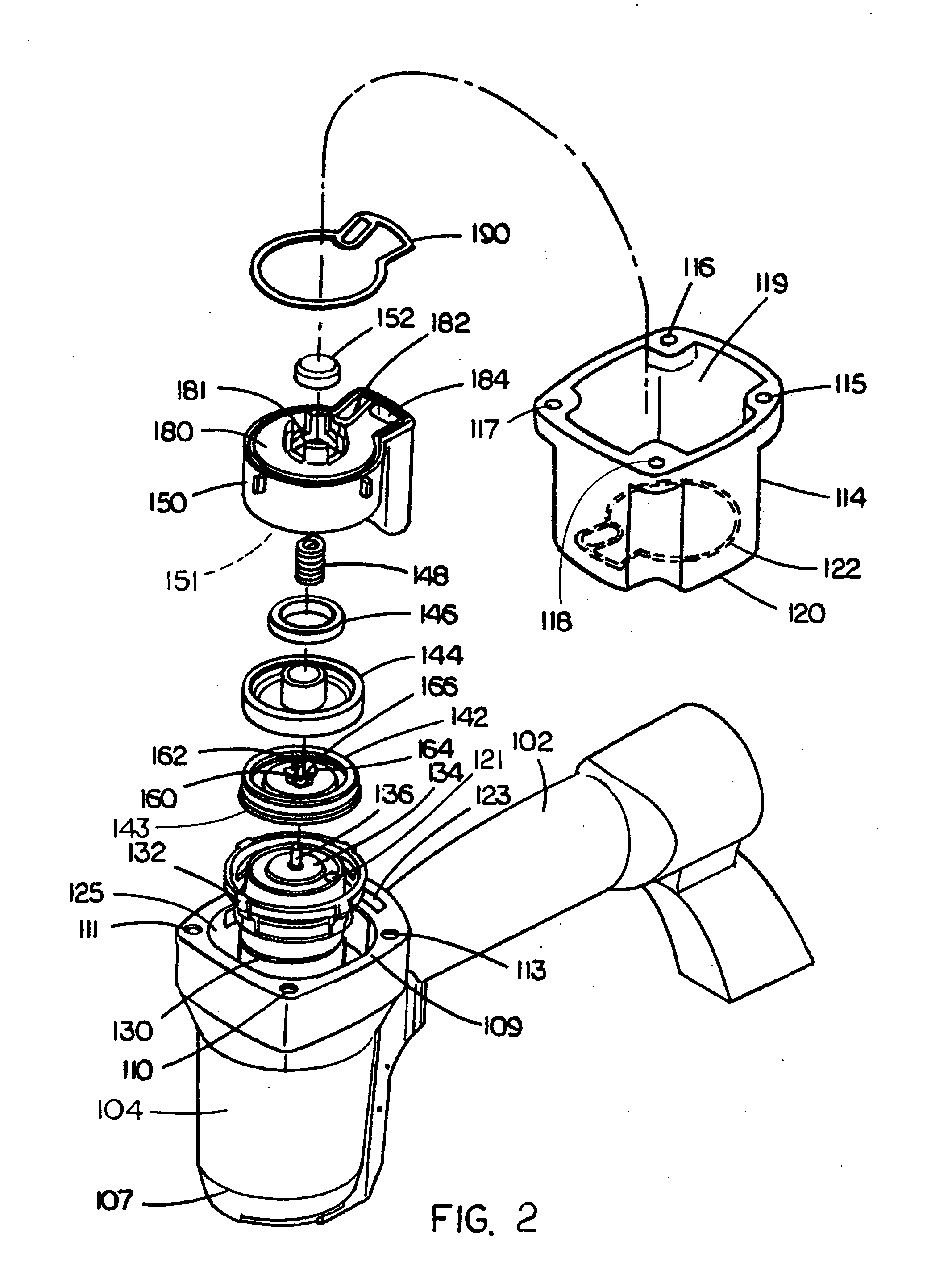
[0035] Referring now to FIG. 2, in the exemplary embodiment the housing 104 defines a housing recessed area 125 within which a piston assembly including a cylinder 130 and a pist...


PUM

PropertyMeasurementUnit
Angleaaaaaaaaaa
Lengthaaaaaaaaaa

Abstract

A contact safety and trigger mechanism for use with a pneumatic fastener in order to permit efficient pneumatic fastener actuation mode selection. A rotating rod is included in a contact safety assembly which is constructed to slide toward/away from a driver housing, defining a piston for securing a fastener disposed within the piston's path of travel. The rotating rod includes a first shoulder or ledge and a second shoulder which is off-set from the first shoulder. The rod may be rotated in order to orientate the selected shoulder, to function as a stop for a pivoting trigger assembly, which is constructed to contact a pneumatic valve, to initiate a fastening event in-which a fastener is driven into a workpiece. The configuration of the rotating rod permits for selection between a contact actuation mode wherein movement of the contact safety initiates securing of a fastener and a sequential actuation mode in which the trigger assembly is manipulated by a user to trigger securing of a fastener after the contact safety has be depressed towards the driver housing.

Description

CROSS REFERENCE TO RELATED APPLICATIONS [0001] The present application claims the benefit under 35 U.S.C. § 119(e) of U.S. Provisional Patent Application Ser. No. 60 / 546,685, entitled “Oil Free Head Valve for Pneumatic Nailers and Staplers,” filed Feb. 20, 2004 which is herein incorporated by reference in its entirety.FIELD OF THE INVENTION [0002] The present invention generally relates to the field of power tools, and particularly to a dual mode actuation mechanism for pneumatic fasteners, such as pneumatic nailers and staplers. BACKGROUND OF THE INVENTION [0003] Fastener devices, such as pneumatic or combustion fasteners, permit efficient securing of fasteners. For instance, a pneumatic fastener may be utilized to secure two workpieces together via a nail. Users of these devices often wish to select between a sequential actuation / firing mode in-which the user is required to pull or draw the trigger to cause the driving of a fastener or a contact actuation / firing mode “bump-mode” i...

Claims


Application Information

Patent Timeline
IPC IPC(8): B25C1/00B25C1/04B25C1/14
CPCB25C1/008B25C1/04B25C1/047B25C1/042
Inventor TERRELL, TIMOTHY E.SMITH, TIMOTHY C.
Owner BLACK & DECKER INC
Why Eureka
Try Eureka