Self-propelling cleaner

a self-propelling cleaner and cleaner technology, applied in the direction of cleaning filter means, cleaning action control, electric equipment installation, etc., can solve the problems of conventional self-propelling cleaners, suction is not taken in sufficient safety measures, and the self-propelling cleaner may collide, so as to reduce the impact of collision

Inactive Publication Date: 2005-09-01
FUNAI ELECTRIC CO LTD
View PDF0 Cites 11 Cited by
  • Summary
  • Abstract
  • Description
  • Claims
  • Application Information

AI Technical Summary

Benefits of technology

[0006] However, a self-propelling cleaner may collide with furniture or the like that is placed in a cleaning area while it cleans the cleaning area that was set by a user by moving there. To prevent the main body or a hit piece of furniture or the like from being damaged, a buffer material or the like for reducing impact of a collision is attached to the periphery of the main body of a self-propelling cleaner. Therefore, the collision between the self-propelling cleaner and furniture or the like is not problematic in itself. However, the following problem may occur. Impact of a collision between a self-propelling cleaner and a table, for example, causes a lighted cigarette to drop from an ashtray that is placed on the table, and the lighted cigarette is sucked through the suction mouth. The dust in the dust room catches fire from the lighted cigarette to cause a fire. In other words, conventional self-propelling cleaners have a problem that a sufficient safety measure is not taken against suction of a lighted cigarette or the like.

Problems solved by technology

However, a self-propelling cleaner may collide with furniture or the like that is placed in a cleaning area while it cleans the cleaning area that was set by a user by moving there.
However, the following problem may occur.
In other words, conventional self-propelling cleaners have a problem that a sufficient safety measure is not taken against suction of a lighted cigarette or the like.
However, no technique for switching between such dust rooms has been proposed yet.

Method used


Image

  • Self-propelling cleaner
  • Self-propelling cleaner
  • Self-propelling cleaner

Examples


Embodiment Construction

[0016] A self-propelling cleaner according to an embodiment of the present invention will be hereinafter described.

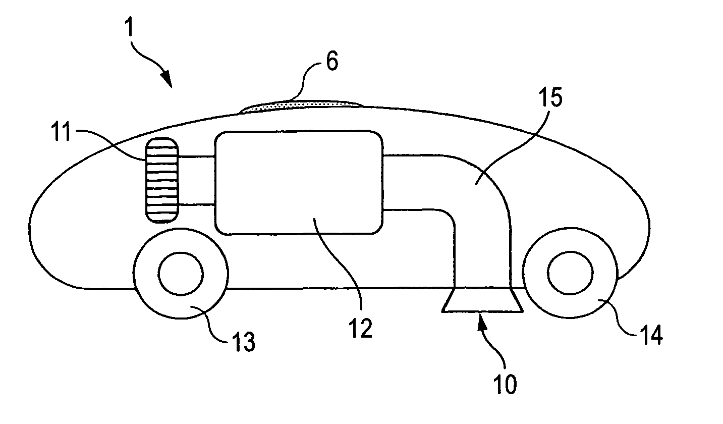
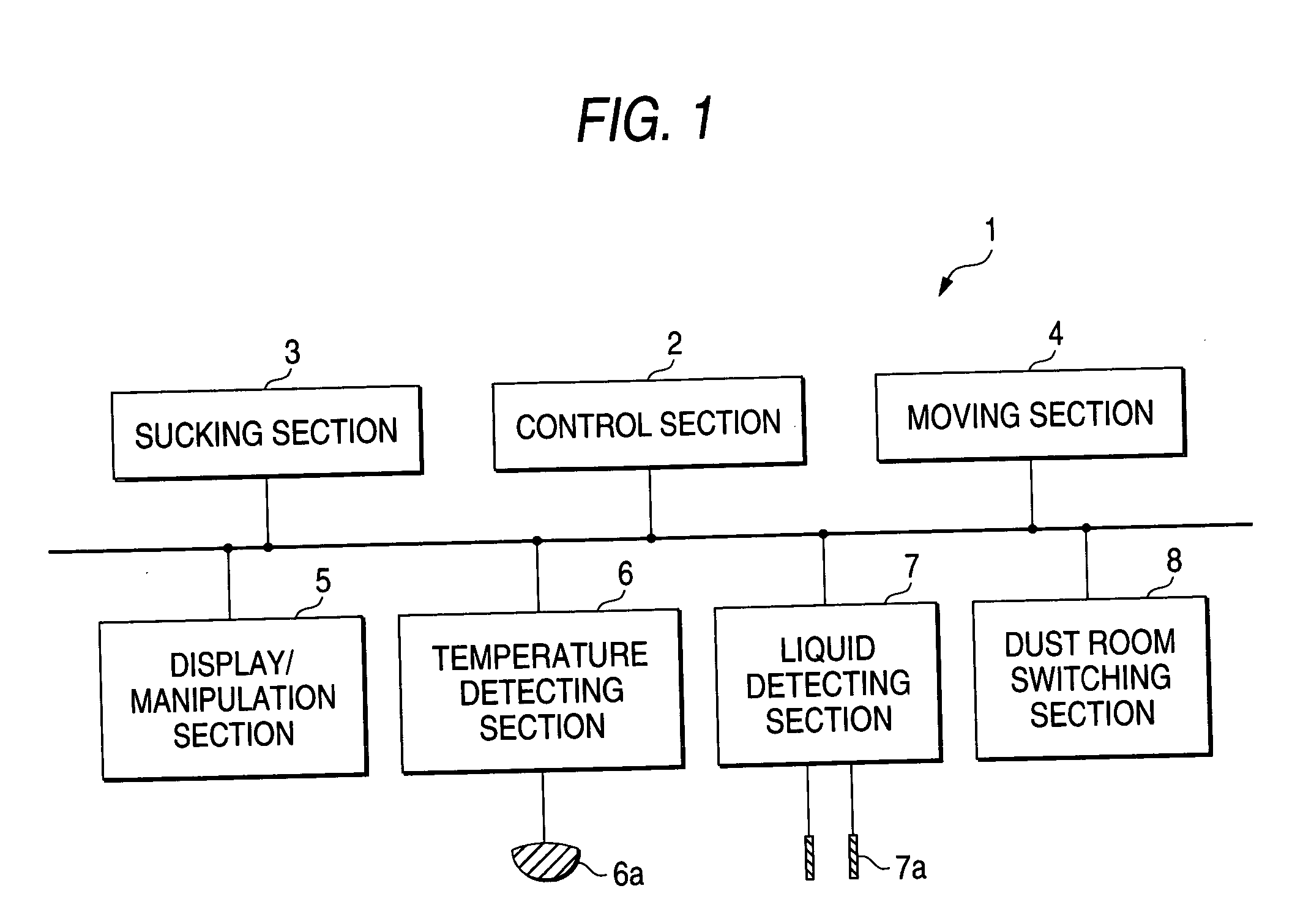
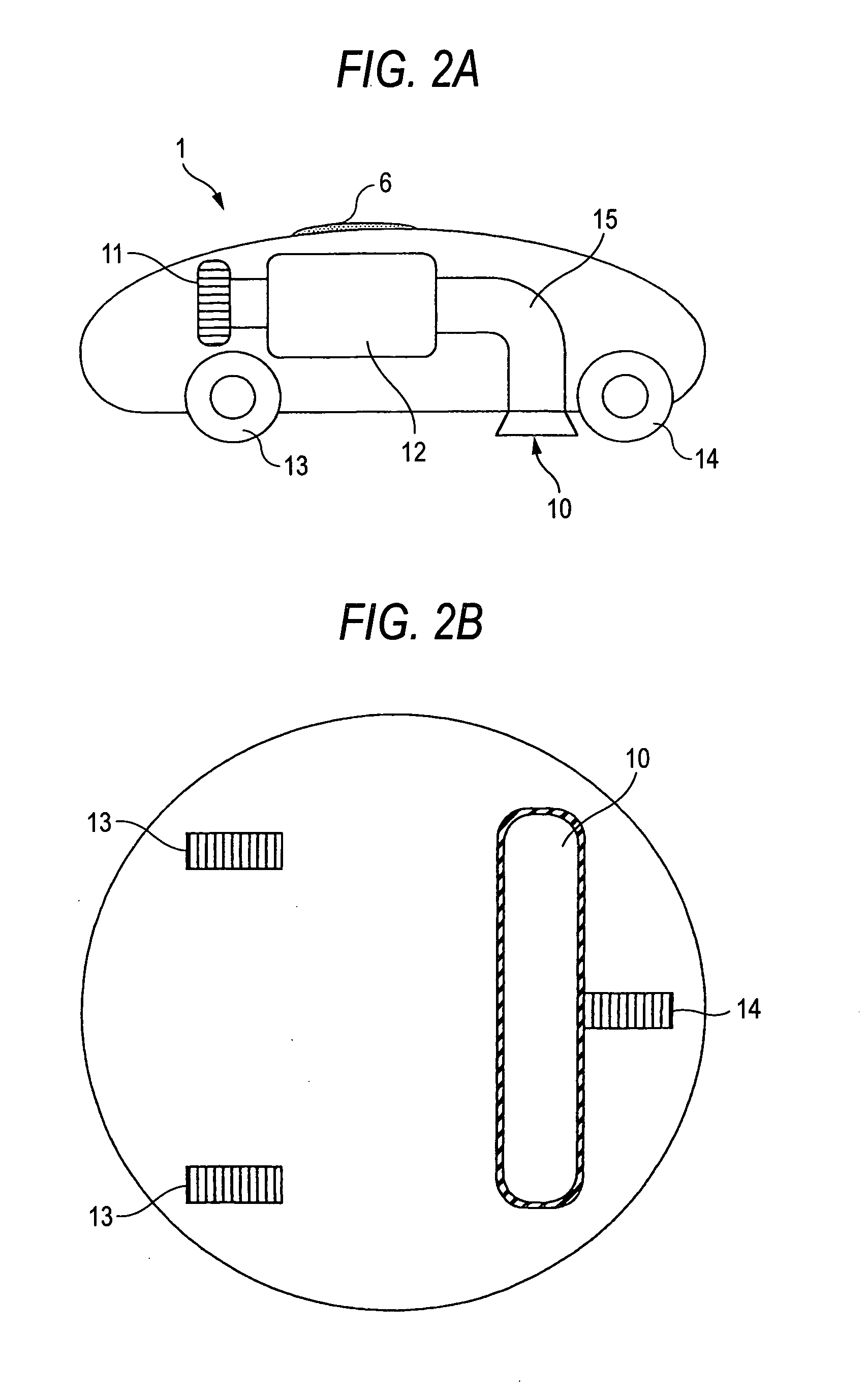
[0017]FIG. 1 is a block diagram showing the configuration of the main part of the self-propelling cleaner according to the embodiment of the invention. FIGS. 2A and 2B are schematic diagrams showing the internal structure of the self-propelling cleaner according to the embodiment. FIG. 2A is a side sectional view and FIG. 2B is a bottom view. The self-propelling cleaner 1 according to the embodiment is equipped with a control section 2 for controlling the operation of the main body, a sucking section 3 for sucking dust into the main body, a moving section 3 for causing the main body to move autonomously, a display / manipulation section 5 for displaying the status of the main body and receiving a manipulation input to the main body, a temperature detecting section 6 for judging whether the temperature of an object that has been sucked into the main body is higher than a ...


PUM


Abstract

When detecting suction of a lighted object such as a cigarette or a match, a self-propelling cleaner 1 sends it to a dust room 12a by controlling a valve 8a. The self-propelling cleaner 1 collects ordinary dust such as dust and wastepaper into a dust room 12b by controlling the valve 8a. Since a lighted object such as a cigarette and ordinary dust are thus sent to two different dust rooms in a discriminated manner, even if a lighted object such as a cigarette is sucked other dust in the dust room can be prevented from catching fire from it, whereby the self-propelling cleaner is made safer from suction of a lighted object.

Description

BACKGROUND OF THE INVENTION [0001] 1. Field of the Invention [0002] The present invention relates to a self-propelling cleaner that cleans a cleaning area by sucking dust existing there by causing a main body to move autonomously in the cleaning area. [0003] 2. Description of the Related Art [0004] Among vacuum cleaners for cleaning dust such as dust on a floor or the like is one in which the main body is equipped with two dust rooms for collecting dust that is sucked into the main body, one dust room being used as a dust room for collecting ordinary dust such as dust and wastepaper and the other being as a dust room for collecting special dust such as metal pieces and glass pieces (refer to JP-A-7-047042). The vacuum cleaner described in Patent document 1 is such that a user chooses a dust room for collecting sucked dust in accordance with a type of dust that is about to be sucked. [0005] In recent years, self-propelling cleaners have been put in practical use that clean a cleaning...

Claims


Application Information

Patent Timeline
Patent Type & Authority Applications(United States)
IPC IPC(8): A47L9/28A47L9/00
CPCA47L9/2805A47L2201/06A47L9/2889A47L9/2852
Inventor TAKENAKA, HIROYUKI
Owner FUNAI ELECTRIC CO LTD
Why Eureka
Try Eureka