Liquid ejecting apparatus

a technology of liquid ejector and ejector plate, which is applied in printing and other directions, can solve the problems of increasing cost, affecting printing efficiency, and affecting printing efficiency, and achieving the effect of improving printing efficiency

Active Publication Date: 2012-01-19
SEIKO EPSON CORP
View PDF2 Cites 6 Cited by
  • Summary
  • Abstract
  • Description
  • Claims
  • Application Information

AI Technical Summary

Benefits of technology

[0009]An advantage of some aspects of the invention is to provide a liquid ejecting apparatus that can protect a liquid ejecting head and makes it possible to sh

Problems solved by technology

In such a printer, if each of a plurality of caps corresponding to a plurality of recording heads has a function for sucking ink, the structure of the printer is complex, which results in an increase in cost.
In such a cas

Method used


Image

  • Liquid ejecting apparatus
  • Liquid ejecting apparatus
  • Liquid ejecting apparatus

Examples


Embodiment Construction

[0041]With reference to the accompanying drawings, exemplary embodiments of the present invention will now be explained in detail. Although various specific features are explained in the following exemplary embodiments of the invention for the purpose of disclosing preferred modes thereof, the scope of the invention is not limited to the specific embodiments described below unless any intention of restriction is explicitly shown. In the following description, an ink-jet recording apparatus is taken as an example of a liquid ejecting apparatus according to an aspect of the invention. The ink-jet recording apparatus is hereinafter simply referred to as a “printer”.

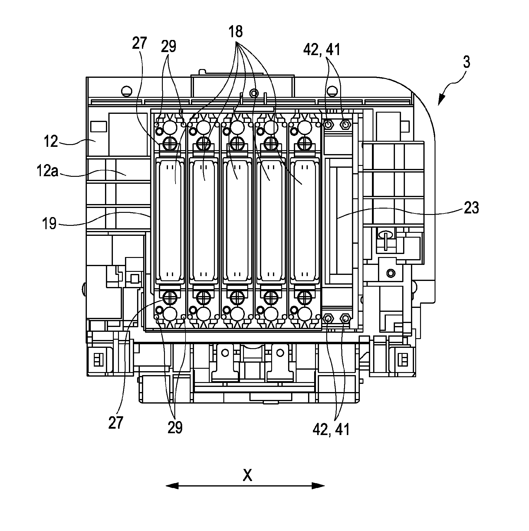
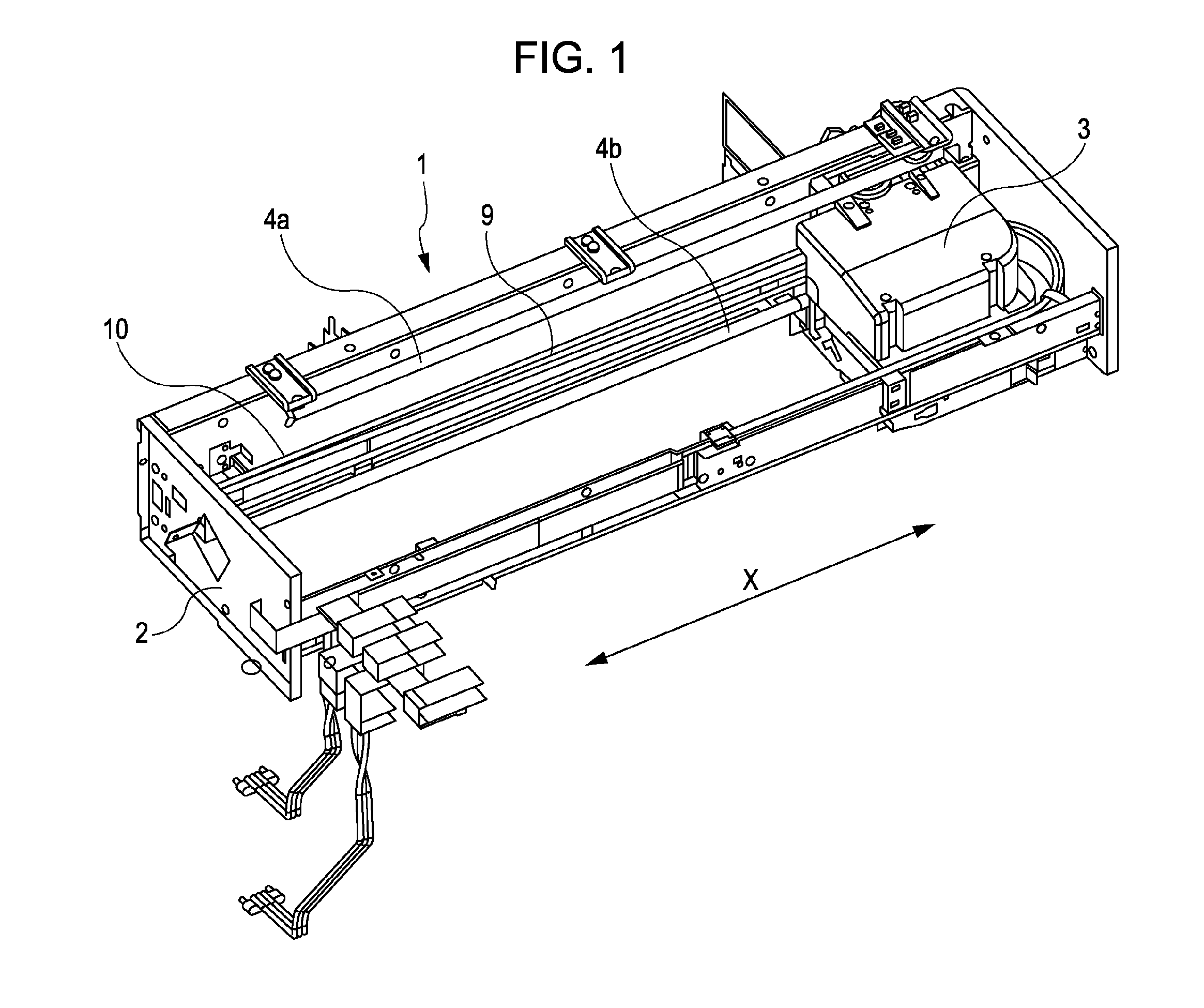
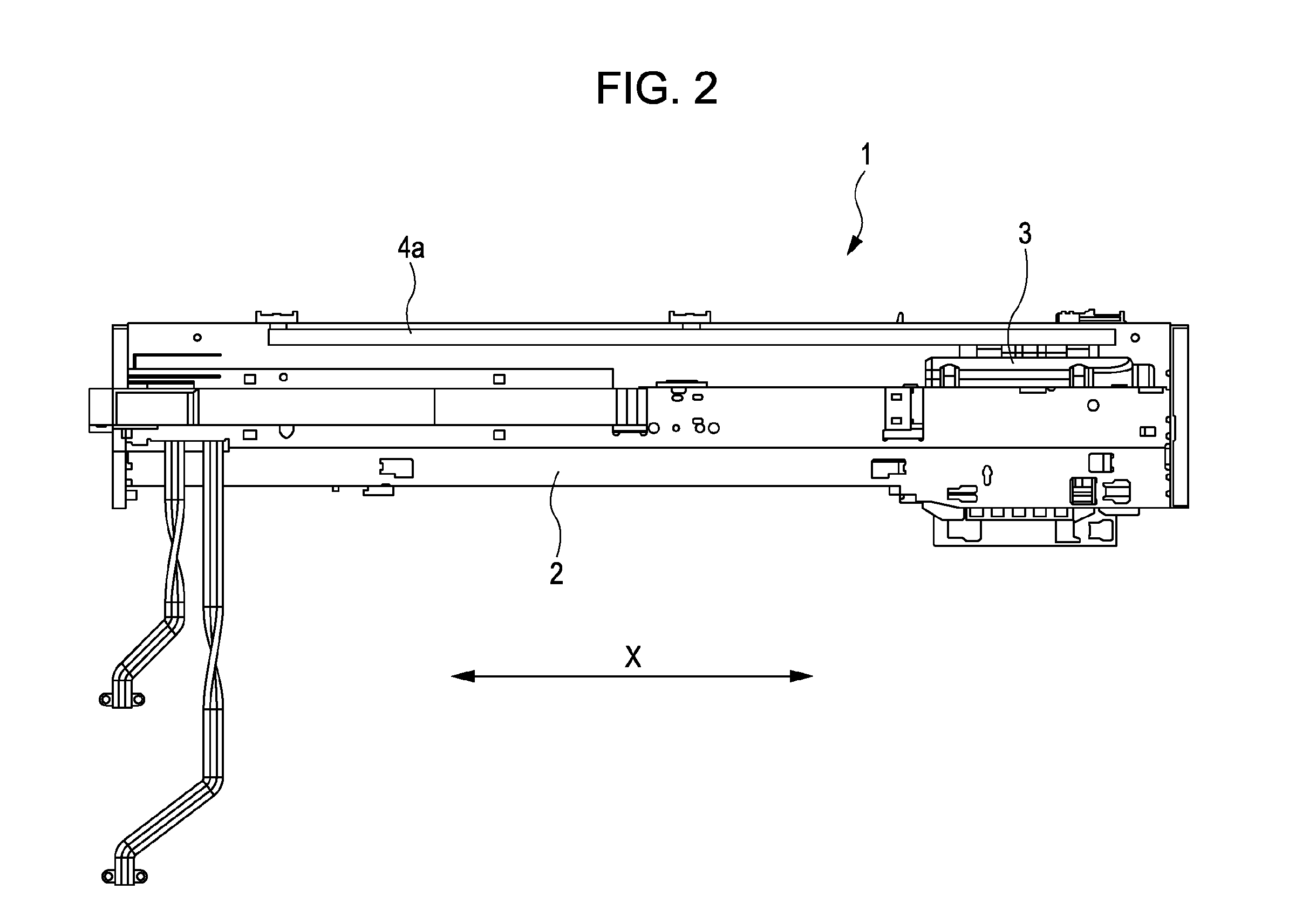
[0042]FIG. 1 is a perspective view that schematically illustrates an example of a part of the inner structure of a printer 1. FIG. 2 is a front view of the printer 1. FIG. 3 is a plan view of the printer 1. FIG. 4 is a right side view of the printer 1. The printer 1 illustrated in these drawings ejects ink, which is a kind o...


PUM


Abstract

At a front-end side opposite to a head-fixing-member-attachment side, a protection member has an inclined plane sloped up from a head side toward the opposite outer side in a direction in which liquid ejecting heads are arranged in a row. The surface of the front end is located at a position that is not closer to a head-fixing member in comparison with the nozzle surface of each of the liquid ejecting heads attached to the head-fixing member or level therewith. A recess is formed at a part of the inclined plane. In a state in which one of the caps faces the protection member and, in addition, each of the remaining caps is in contact with the nozzle surface of the liquid ejecting head, a part of the cap facing the protection member is in the recess, which ensures that the cap is not in contact with the protection member.

Description

[0001]The entire disclosure of Japanese Patent Application No: 2010-159680, filed Jul. 14, 2010 and Japanese Patent Application No: 2010-197836, filed Sep. 3, 2010 are expressly incorporated by reference herein.BACKGROUND[0002]1. Technical Field[0003]The present invention relates to a liquid ejecting apparatus that is equipped with a plurality of liquid ejecting heads for ejecting liquid retained in pressure chambers through nozzles by applying a pressure change in the pressure chambers, which are in communication with the nozzles.[0004]2. Related Art[0005]A liquid ejecting apparatus is a machine that is provided with a liquid ejecting head that can eject (discharge) liquid. Having such a liquid ejecting head, a liquid ejecting apparatus is capable of ejecting various kinds of liquid. An example of a liquid ejecting apparatus is an image recording apparatus such as an ink-jet printer. An ink-jet printer is provided with an ink-jet recording head, which is an example of various kinds...

Claims


Application Information

Patent Timeline
IPC IPC(8): B41J2/165
CPCB41J2/16532B41J2/16511
Inventor KITAMURA, KENICHIYAJIMA, YASUSHIHARADA, NORIHITOHIRUMA, DAISUKEHAMANO, RYOHAGIWARA, HIROYUKI
Owner SEIKO EPSON CORP
Why Eureka
Try Eureka