Liquid-cooled-type cooling device

a cooling device and liquid cooling technology, applied in the direction of semiconductor devices, lighting and heating apparatus, basic electric elements, etc., can solve the problem that the fin cannot be accurately disposed at a predetermined position, and achieve the effect of minimizing the flow velocity drop, and shifting the position

Active Publication Date: 2010-03-04
RESONAC CORP
View PDF12 Cites 24 Cited by
  • Summary
  • Abstract
  • Description
  • Claims
  • Application Information

AI Technical Summary

Benefits of technology

[0016]According to the liquid-cooled-type cooling device of par. 1), projections which come into contact with front and rear end portions of the fin to thereby position the fin in the front-rear direction are provided on the inner surface of the top wall of the casing and / or the inner surface of the bottom wall of the casing. Thus, positional shift of the fin in the front-rear direction can be prevented during manufacture of the cooling device. Accordingly, the fin can be accurately disposed at a predetermined position. Further, since the projections are provided on the inner surface of the top wall of the casing and / or the inner surface of the bottom wall of the casing at positions shifted, in the left-right direction, from an inner surface region corresponding to the heat-generating-body mounting region, the projections do not decrease the flow velocity of the cooling liquid flowing through flow channels at positions corresponding to the heat-generating-body mounting region, among the flow channels, which are formed by the fin and extend in the front-rear direction, whereby a drop in the effect of cooling the heat-generating body mounted in the heat-generating-body mounting region is prevented.
[0017]According to the liquid-cooled-type cooling device of par. 2), the front-side projections with which the front end portion of the fin comes into contact are provided such that they are spaced from one another along the left-right direction; the rear-side projections with which the rear end portion of the fin comes into contact are provided such that they are spaced from one another in the left-right direction; and the rear-side projections are shifted from the front-side projections along the left-right direction. Therefore, it is possible to minimize a drop in the flow velocity of the cooling liquid flowing through flow channels in which the projections are formed, among the flow channels, which are formed by the fin and extend in the front-rear direction.
[0018]According to the liquid-cooled-type cooling devices of par. 3) and par. 4), the number of the projections required to prevent positional shift of the fin in the front-rear direction during manufacture of the cooling device can be minimized. Accordingly, it is possible to minimize the drop in the flow velocity of the cooling liquid flowing through flow channels in which the projections are formed, among the flow channels, which are formed by the fin and extend in the front-rear direction.
[0019]According to the liquid-cooled-type cooling device of par. 5), the fin is a corrugated fin which includes wave crest portions, wave trough portions, and connection portions connecting the wave crest portions and the wave trough portions; and the width of the front-side projections and the rear-side projections as measured along the left-right direction is less than two times the spacing between two wave crest portions of the fin adjacent to each other and between two wave trough portions thereof adjacent to each other, and is greater than the spacing between a wave crest portion of the fin and a wave trough portion thereof adjacent to the wave crest portion. Therefore, positional shift of the fin in the front-rear direction, which would otherwise occur during manufacture of the cooling device, can be prevented reliably.
[0020]According to the liquid-cooled-type cooling device of par. 6), the height of the front-side projections and the rear-side projections is greater than the thickness of the fin and equal to or less than half the height of the fin. Therefore, positional shift of the fin in the front-rear direction, which would otherwise occur during manufacture of the cooling device, can be prevented reliably. In addition, it is possible to minimize the drop in the flow velocity of the cooling liquid flowing through flow channels in which the projections are formed, among the flow channels, which are formed by the fin and extend in the front-rear direction.
[0021]According to the liquid-cooled-type cooling device of par. 8), portions of the front-side projections and the rear-side projections bite on the fin, whereby minute play of the fin can be prevented.

Problems solved by technology

However, the liquid-cooled-type cooling device disclosed in the above-mentioned publication has a problem in that the position of the fin may shift in the front-rear direction at the time of manufacture of the cooling device, and, therefore, the fin cannot be accurately disposed at a predetermined position.

Method used


Image

  • Liquid-cooled-type cooling device
  • Liquid-cooled-type cooling device
  • Liquid-cooled-type cooling device

Examples


Embodiment Construction

[0026]A preferred embodiment of the present invention will next be described with reference to the drawings.

[0027]In the following description, the term “aluminum” encompasses aluminum alloys in addition to pure aluminum.

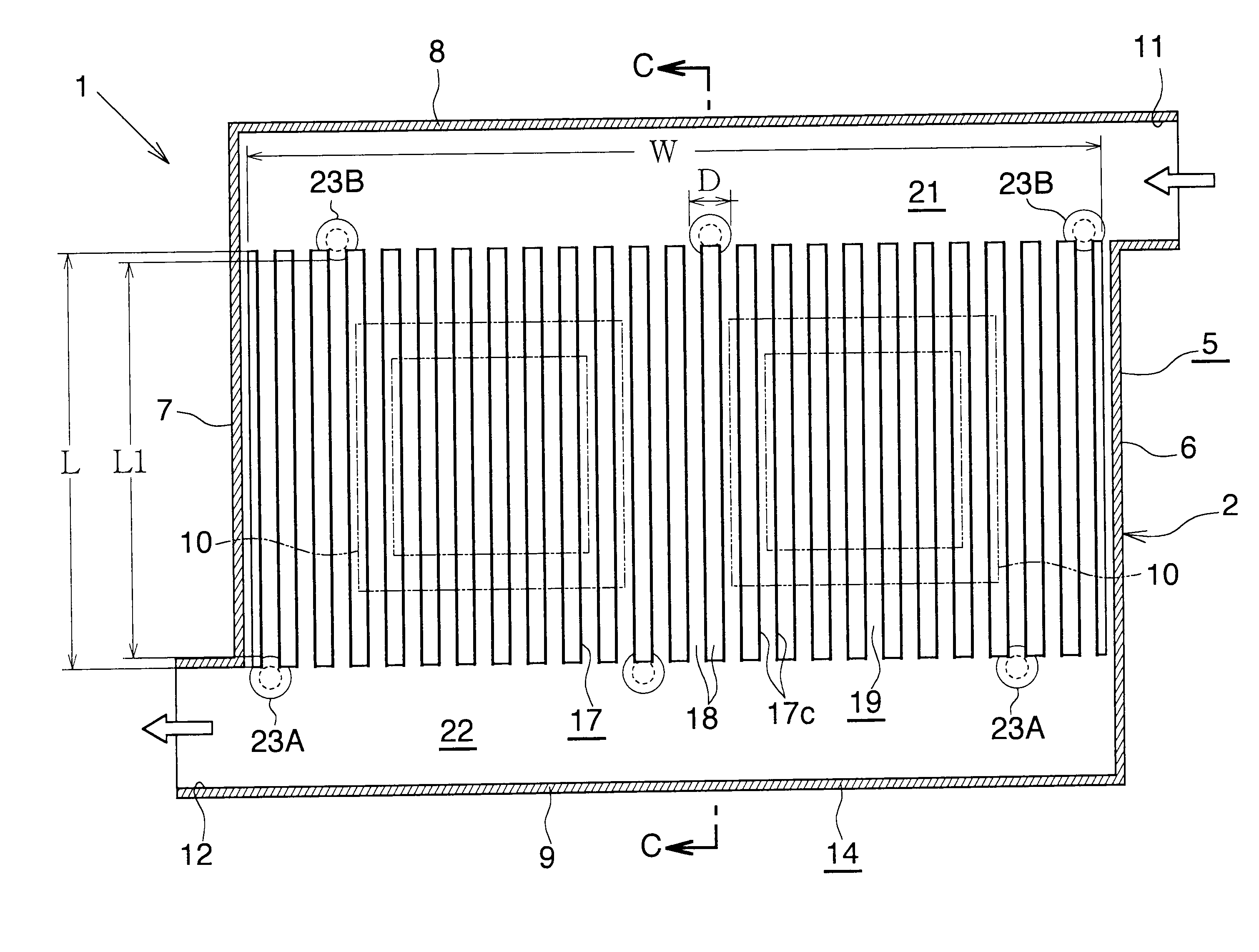
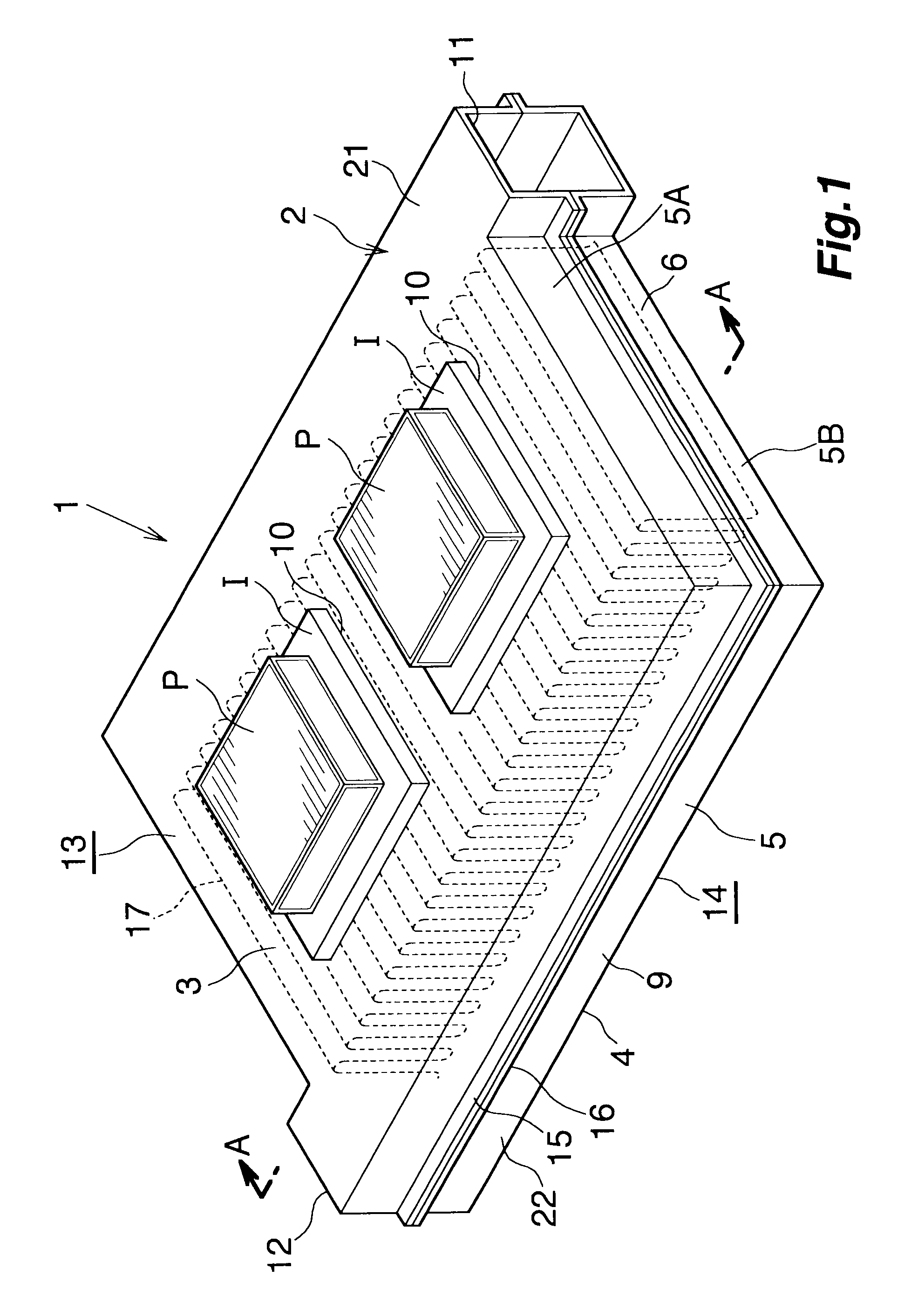
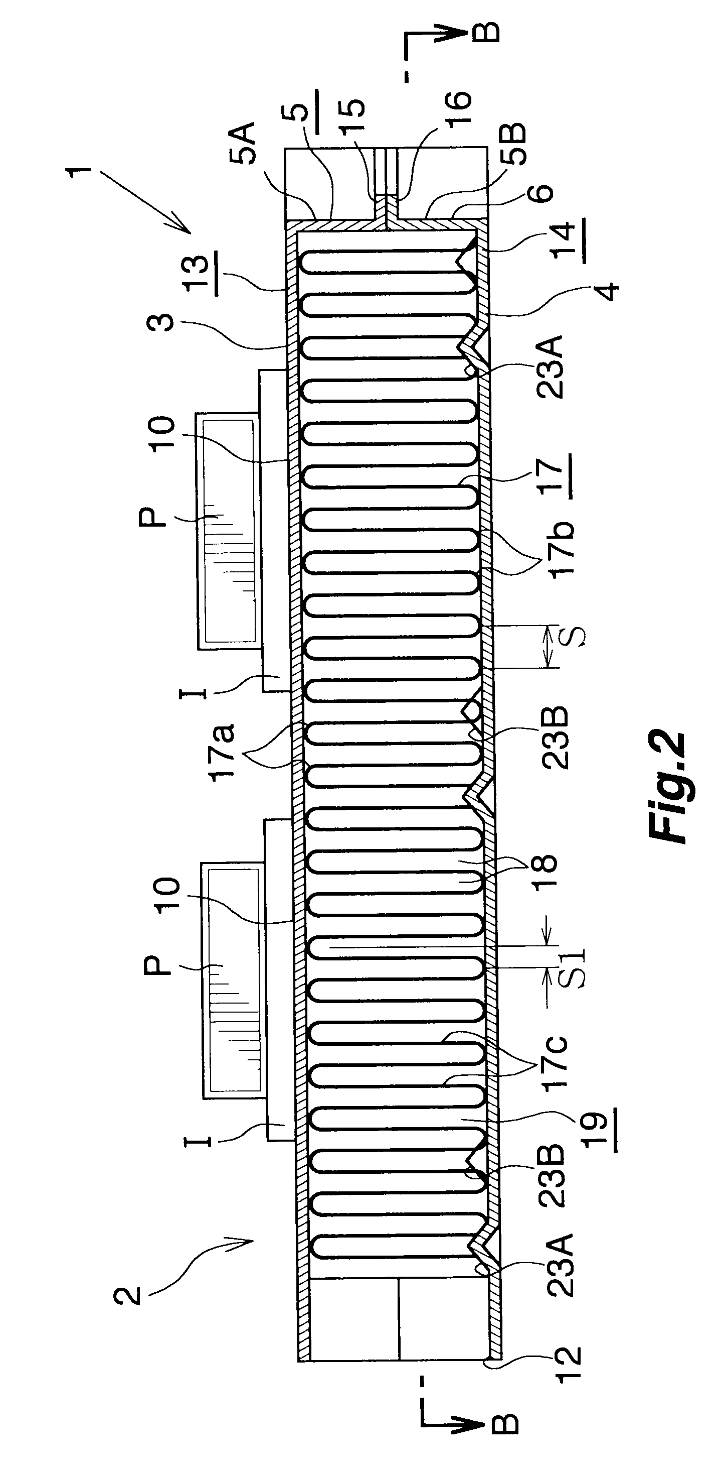
[0028]FIGS. 1 to 4 show a state in which semiconductor devices, each of which is a heat-generating body, are mounted on a liquid-cooled-type cooling device according to the present invention.

[0029]In FIGS. 1 to 4, a liquid-cooled-type cooling device 1 has a casing 2 composed of a top wall 3, a bottom wall 4, and a peripheral wall 5. A plurality of heat-generating-body mounting regions 10 are provided on the outer surface of the top wall 3 of the casing 2 such that the regions are separated from one another in the left-right direction. The peripheral wall 5 of the casing 2 includes a right side wall 6, which extends in the front-rear direction and stands vertically; a left side wall 7, which extends in the front-rear direction, stands vertically, and is positioned in...


PUM


Abstract

A liquid-cooled-type cooling device includes a casing which has a cooling-liquid inlet formed at a rear end portion of the casing and a cooling-liquid outlet formed at a front end portion of the casing. A corrugated fin for forming a plurality of flow channels through which a cooling liquid flows from the rear side toward the front side is disposed within the casing to be located between the cooling-liquid inlet and the cooling-liquid outlet. A heat-generating-body mounting region is provided on an outer surface of a top wall of the casing. Projections which come into contact with front and rear end portions of the corrugated fin to thereby position the corrugated fin in the front-rear direction are provided on an inner surface of the bottom wall of the casing at positions shifted, in the left-right direction, from an inner surface region corresponding to the heat-generating-body mounting region.

Description

BACKGROUND OF THE INVENTION[0001]The present invention relates to a liquid-cooled-type cooling device for cooling a heat-generating body composed of an electronic component such as a semiconductor device.[0002]In the present specification and appended claims, the side toward which cooling liquid flows within flow channels formed by a fin (the lower side of FIG. 3) will be referred to as “front,” and the opposite side will be referred to as “rear.” Also, the upper, lower, left-hand, and right-hand sides of FIG. 2 will be referred to as “upper,”“lower,”“left,” and “right,” respectively.[0003]There has been conventionally known a liquid-cooled-type cooling device for electronic components (see Japanese Patent Application Laid-Open (kokai) No. 2001-352025). The known liquid-cooled-type cooling device includes a casing which is composed of a top wall, a bottom wall, and a peripheral wall and which has a cooling-liquid inlet formed at a rear end portion of the casing and a cooling-liquid ...

Claims


Application Information

Patent Timeline
Patent Type & Authority Applications(United States)
IPC IPC(8): F28D15/00F28F7/00H01L23/473
CPCF28F3/025F28F3/12H01L21/4882H01L23/473H01L2924/0002F28F2265/32H01L2924/00F28D15/02H01L23/34
Inventor MORI, SHOGOOBARA, HIDEYASUKURIBAYASHI, TAIZOTAMURA, SHINOBU
Owner RESONAC CORP
Why Eureka
Try Eureka