This helps you quickly interpret patents by identifying the three key elements:
Problems solved by technology
Method used
Benefits of technology
Benefits of technology
The present invention aims to provide an inductor that improves productivity. The invention involves a method of manufacturing an inductor that reduces positional shifting between magnetic members and a coil. This is achieved by using a single fixation member to bind and fix the magnetic members to each other and to a main body, suppressing any relative shift in position. This results in a reduction of workload required for the process and ensures successful positioning of the magnetic member and coil.
Problems solved by technology
When a closed magnetic path is formed in this sort of inductor by inserting a part of the core into the coil, only a simple winding of the tape will fail to prevent relative positional shift of the coil and the core, and will fail to achieve target specification.
It has therefore been necessary to spend some additional workload and to prepare a specialized jig used for such work for every product, which has caused a problem from the viewpoint of productivity.
Method used
Image
Click on the blue label to locate the original text in one second.
Reading with bidirectional positioning of images and text.
Examples
first embodiment
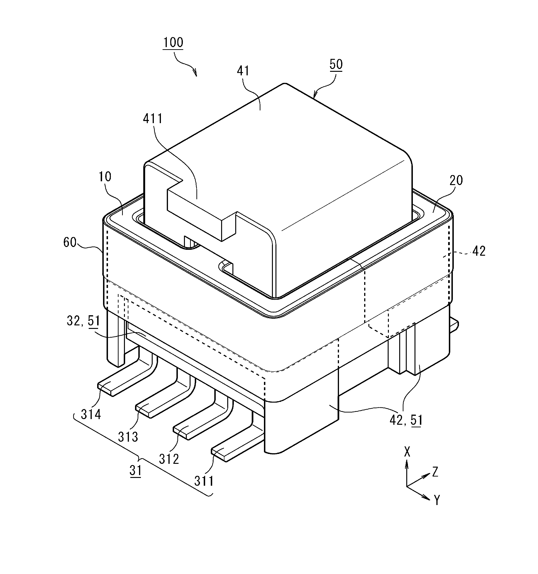
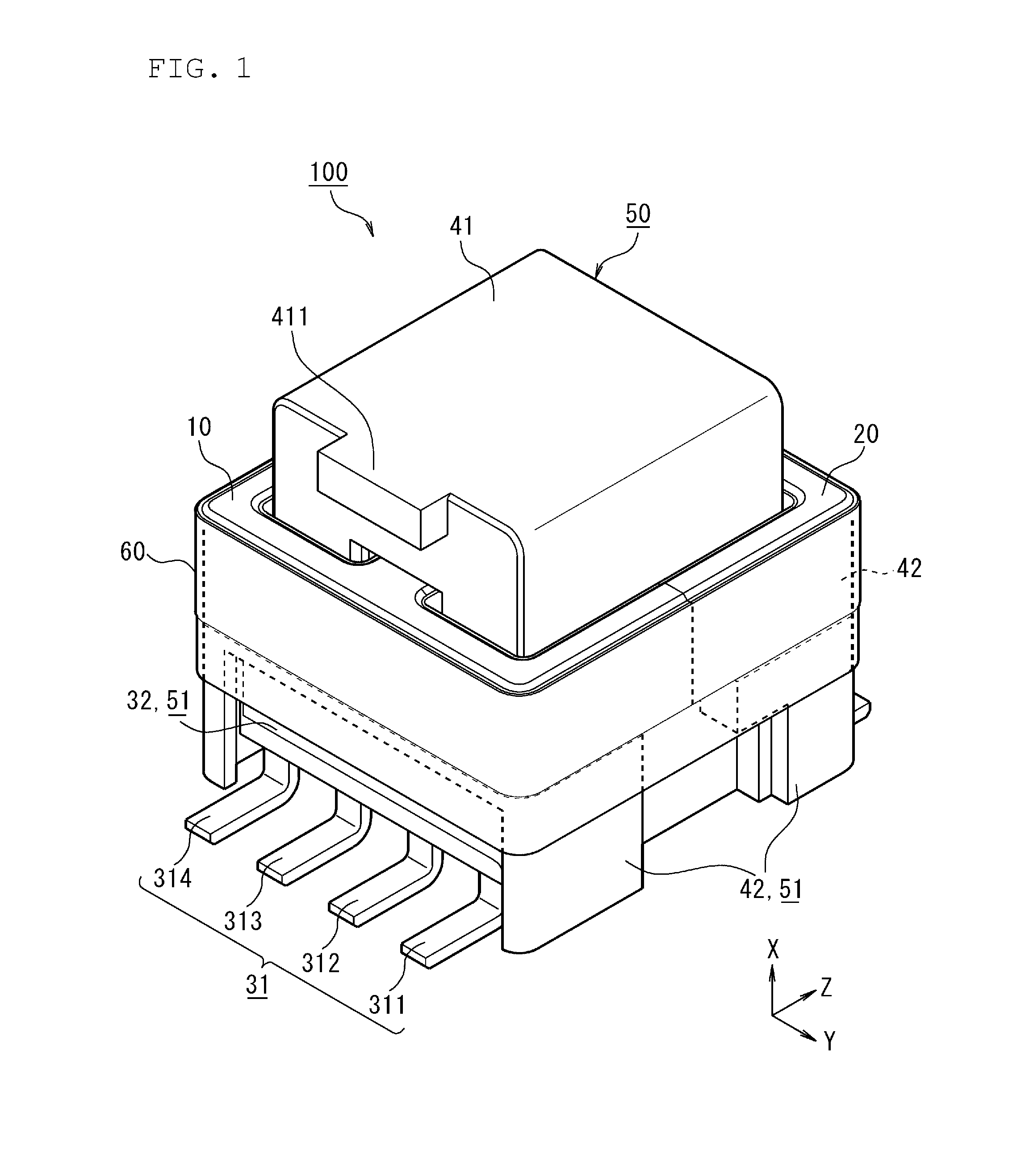
[0031]An inductor 100 of the first embodiment will be outlined referring to FIG. 1, FIG. 2, FIG. 5 and FIG. 6.
[0032]FIG. 1 is a perspective view illustrating the inductor 100 of the first embodiment viewed from the negative side on Z-axis. FIG. 2 is a perspective view illustrating the inductor 100 of the first embodiment viewed form the positive side on Z-axis. FIG. 5 is a bottom view of the inductor 100. FIG. 6 is a cross-sectional view taken along line VI-VI in FIG. 5.
[0033]The inductor 100 has a pair of magnetic members (core 10 and core 20), and main body 50 having a coil 71 and a coil 72 configured by a wound wire. A rod-like insertion part 12 of one magnetic member (core 10), out of the pair of magnetic members, is inserted into the coil 71. A rod-like insertion part 22 of the other magnetic member (core 20), out of the pair of magnetic members, is inserted into the coil 72. The core 10 and the core 20 are combined to configure a closed magnetic path, and, the closed magnetic ...
second embodiment
[0129]An inductor 200 of a second embodiment will be outlined below, referring to FIG. 11.
[0130]FIG. 11 is a perspective view illustrating the inductor 200 of the second embodiment. In more details, FIG. 11 is a perspective view of the inductor 200, with the core 20 directed to the nearer side.
[0131]In this embodiment, all components and parts, which are considered to be identical with those in the first embodiment, will be given identical names and reference numerals for the convenience of explanation.
[0132]The inductor 200 of this embodiment is different from the inductor 100 of the first embodiment, in that adhesives 81, 82 are applied at boundary positions between a part of the cover part 41 which protrudes from inside of the frame, configured to contain the core 10 and the core 20, in the direction opposite to the base part 51, and the pair of magnetic members.
[0133]In more details, the adhesive 81 is applied at the boundary position between a point where the outer frame part 1...
PUM
Property
Measurement
Unit
Heat
aaaaa
aaaaa
Tackiness
aaaaa
aaaaa
Abstract
An inductor (100) includes a pair of magnetic members (cores (10, 20)), a main body having coils (71, 72), and a sheet-formed fixation member (60), wherein the fixation member (60) is bound across the cores (10, 20) and the main body, to thereby fix the cores (10, 20) which configure a closed magnetic path, and to thereby fix at least one of the cores (10, 20) to the main body.
Description
[0001]This application is based on Japanese patent application No. 2014-097616, filed on May 9, 2014, the content of which is incorporated hereinto by reference.BACKGROUND[0002]1. Technical Field[0003]The present invention relates to an inductor used in particular for transformer, and a method of manufacturing the inductor.[0004]2. Related Art[0005]There has been known an inductor having a plurality of cores assembled to configure a closed magnetic path, wherein the plurality of cores are fixed by winding a tape around them. This sort of inductor is typically disclosed in JP-U-H05-28012.[0006]According to JP-U-H05-28012, the plurality of cores have trenches provided on the outer circumferential surfaces thereof, and are fixed in an abutted manner by winding the tape while guided by the trench. By virtue of provision of the trench, positional variation of winding may be suppressed, and workload of a worker who winds up the tape may be reduced.[0007]When a closed magnetic path is form...
Claims
Application Information
Patent Timeline
Application Date:The date an application was filed.
Publication Date:The date a patent or application was officially published.
First Publication Date:The earliest publication date of a patent with the same application number.
Issue Date:Publication date of the patent grant document.
PCT Entry Date:The Entry date of PCT National Phase.
Estimated Expiry Date:The statutory expiry date of a patent right according to the Patent Law, and it is the longest term of protection that the patent right can achieve without the termination of the patent right due to other reasons(Term extension factor has been taken into account ).
Invalid Date:Actual expiry date is based on effective date or publication date of legal transaction data of invalid patent.

