Vehicle brake warning system

Inactive Publication Date: 2005-09-01
DINDA MICHAEL WALTER
View PDF16 Cites 4 Cited by
  • Summary
  • Abstract
  • Description
  • Claims
  • Application Information

AI Technical Summary

Benefits of technology

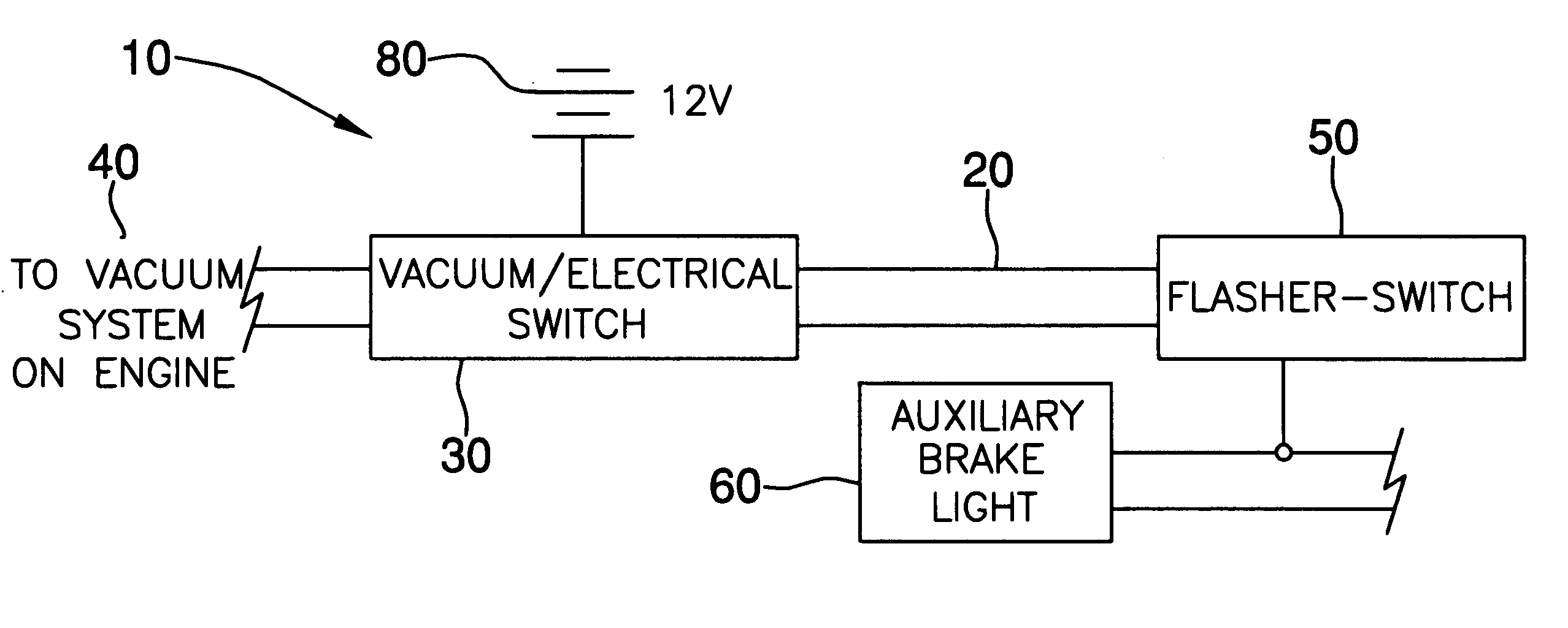
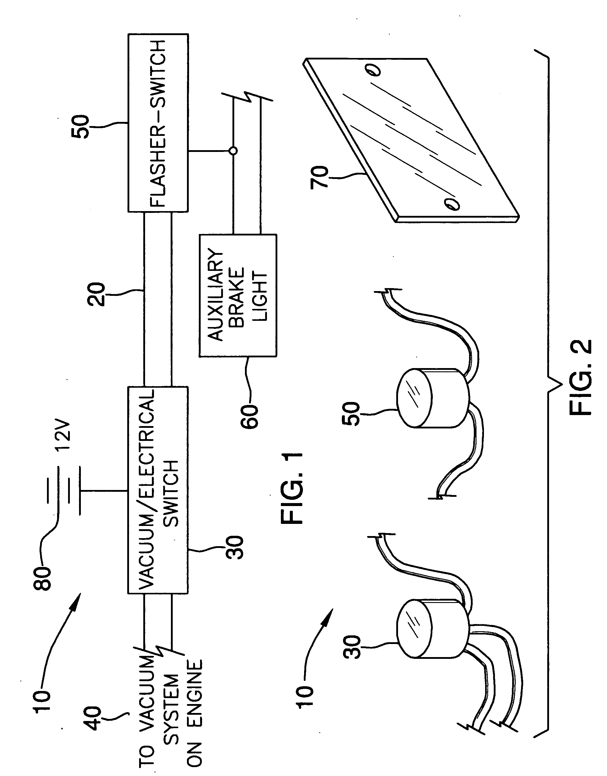
[0013] The flasher-light switch is operably connected to the vacuum/electrical switch for receiving the plurality of signals therefrom, and advantageously indicating when an accelerator pedal is released during operating conditions of a vehicle. The light switch is operably connected to the first vehicle's rear window or deck lid brake light and causes same to flash during an interval defined after an accelerat

Problems solved by technology

The prevalence of rear end collisions has resulted in the installation of high mounted

Method used


Image

  • Vehicle brake warning system
  • Vehicle brake warning system

Examples


Example

[0017] The present invention will now be described more fully hereinafter with reference to the accompanying drawings, in which a preferred embodiment of the invention is shown. This invention may, however, be embodied in many different forms and should not be construed as limited to the embodiment set forth herein. Rather, this embodiment is provided so that this application will be thorough and complete, and will fully convey the true scope of the invention to those skilled in the art. Like numbers refer to like elements throughout the figures.

[0018] The system of this invention is referred to generally in FIGS. 1-2 by the reference numeral 10 and is intended to provide a vehicle brake warning system. It should be understood that the system 10 may be installed on many different land vehicles, and therefore should not be construed as having limited application to only conventional automobiles.

[0019] Referring initially to FIG. 1, the system 10 includes a brake warning system 20 a...


PUM


Abstract

A brake warning system is attachable to a first vehicle and for warning a second vehicle of an anticipated first vehicle braking. The system includes a vacuum or electrical switch operably connected to the first vehicle engine vacuum system and further includes a mechanism for monitoring a vacuum pressure fluctuation thereof. The vacuum switch sends a plurality of signals corresponding to accelerating and non-accelerating modes of the first vehicle and has a flasher light switch operably connected to it for receiving the plurality of signals therefrom for indicating when an accelerator pedal is released. The light switch is operably connected to the first vehicle brake light and flashes during an interval defined after an accelerator pedal is released and before the brake pedal is engaged.

Description

CROSS REFERENCE TO RELATED APPLICATIONS [0001] Not Applicable. STATEMENT REGARDING FEDERALLY SPONSORED RESEARCH OR DEVELOPMENT [0002] Not Applicable. REFERENCE TO A MICROFICHE APPENDIX [0003] Not Applicable. BACKGROUND OF THE INVENTION [0004] 1. Technical Field [0005] This invention relates to a vehicle warning system and, more particularly, to a vehicle brake warning system for notifying a trailing vehicle of imminent braking. [0006] 2. Prior Art [0007] The prevalence of rear end collisions has resulted in the installation of high mounted brake lights on all automobiles manufactured for sale in the United States after 1985. This has been done since it has been demonstrated that placement of brake lights in a trailing driver's field of view reduces the time between a leading vehicle brake light onset and the following vehicle's brake application by approximately 25%. This result is achieved by earlier perception that a braking action is taking place in the leading vehicle. [0008] Av...

Claims


Application Information

Patent Timeline
IPC IPC(8): B60Q1/44B60Q1/50
CPCB60Q1/44
Inventor DINDA, MICHAEL WALTER
Owner DINDA MICHAEL WALTER
Why Eureka
Try Eureka