Electronic termite detector

a termite detector and electronic technology, applied in the field of electronic termite detectors, can solve the problems of not being able to detect the presence of termites visually, affecting the detection effect of termites, and being unable to meet the requirements of the application of the detector, so as to reduce the amount of light received.

Inactive Publication Date: 2005-09-01
LEWIS MARK ROBERT
View PDF10 Cites 20 Cited by
  • Summary
  • Abstract
  • Description
  • Claims
  • Application Information

AI Technical Summary

Benefits of technology

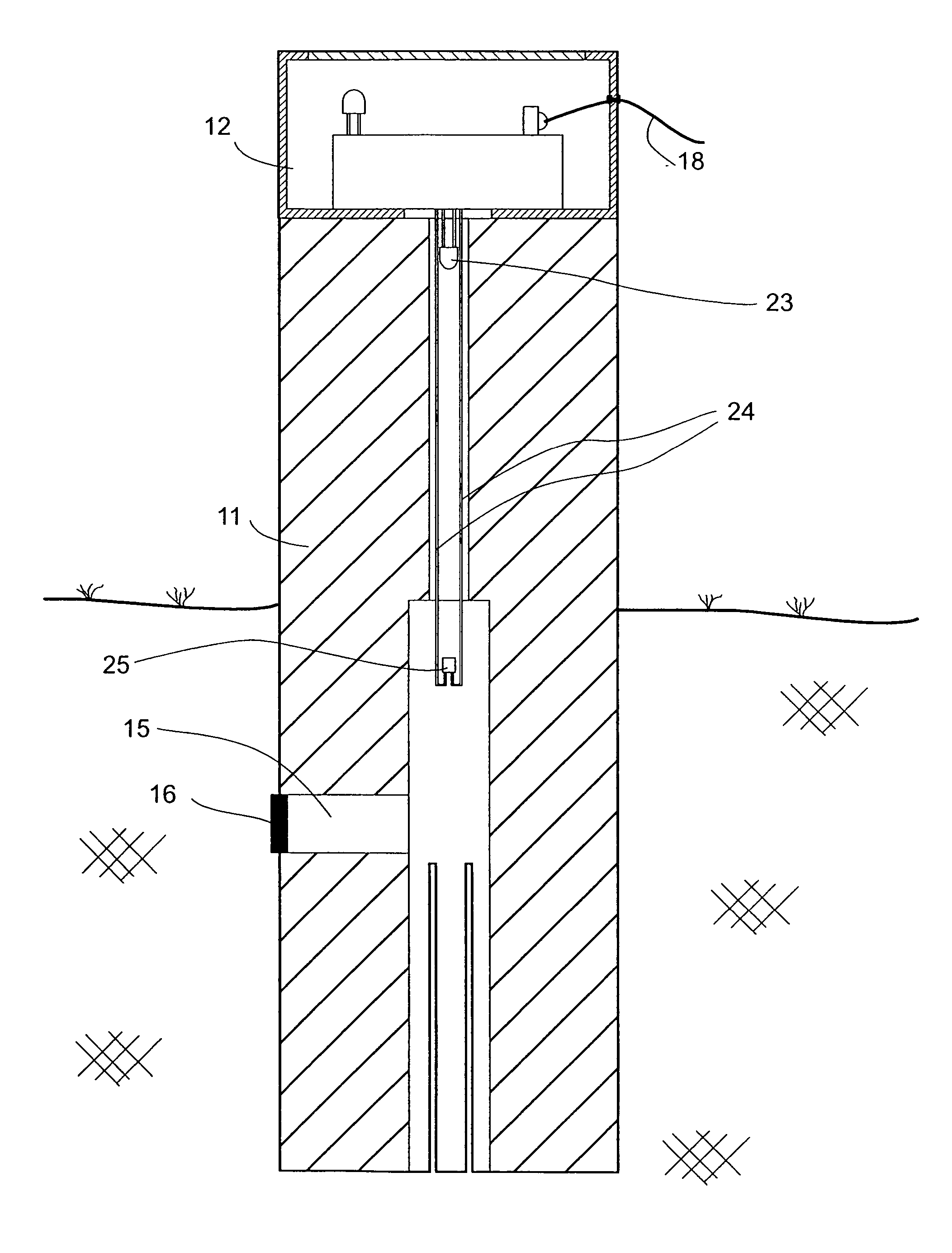
[0026] In use, the device is placed in the ground, in a wall of a building, or other location where the presence of termites is to be detected. If termites come near the device, they will be attracted to the bait in the space within the device. However, as the termites are averse to the light, they will seek to block out the light shining through the passage into the space...

Problems solved by technology

However, as termites live and nest underground or in concealed places, it is not normally possible to detect their presence visually.
Detection of termite activity by routine visual inspection is therefore an unreliable method.
However, due to health and environmental concerns, highly toxic chemicals, such as organo-chlorides, have now been phased out and the permitted chemicals are far less effective and have a much shorter active life.
Physical termite barriers such as stainless steel mesh are relatively expensive, and may lead to a false sense of security since these barriers are known to fail.
However, such toxic baits often fail to destroy the entire colony.
Furthermore, the checking of bait stations is time consuming and tedious, and m...

Method used


Image

  • Electronic termite detector
  • Electronic termite detector
  • Electronic termite detector

Examples


Embodiment Construction

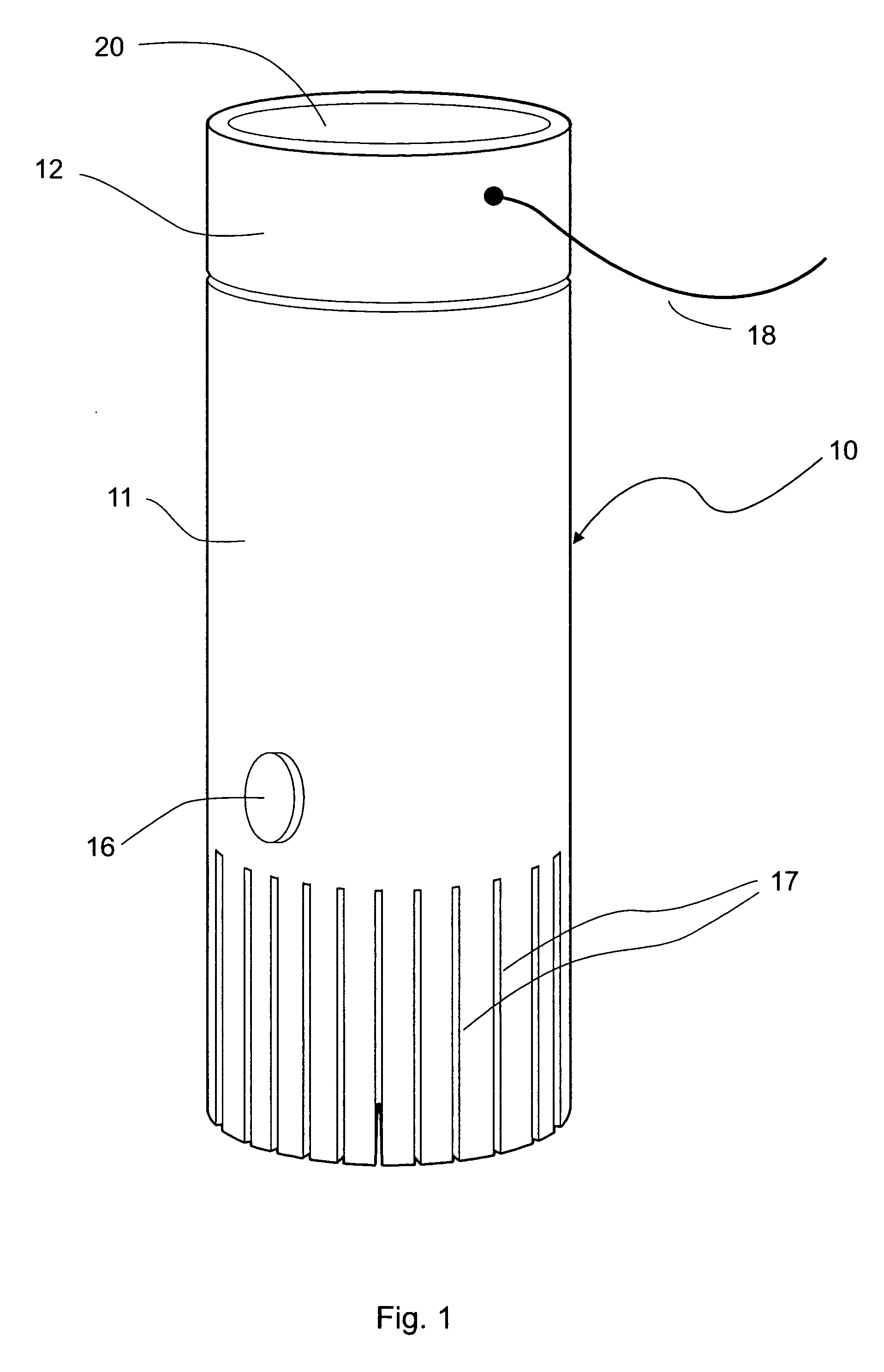
[0034] As shown in the drawings, a termite detection device 10 according to one embodiment of the invention is of generally cylindrical form, and comprises a lower tubular portion (hereafter referred to as a “peg”) 11, and an upper cap portion (hereafter referred to as the “cap”) 12. The cap 12 is located on top of the peg 11, and may be affixed thereto by any suitable means, e.g. a threaded connection, a bayonet mount, a clip or magnetic catch, silicon adhesive, or other suitable means. Preferably, cap 12 is detachable from peg 11.

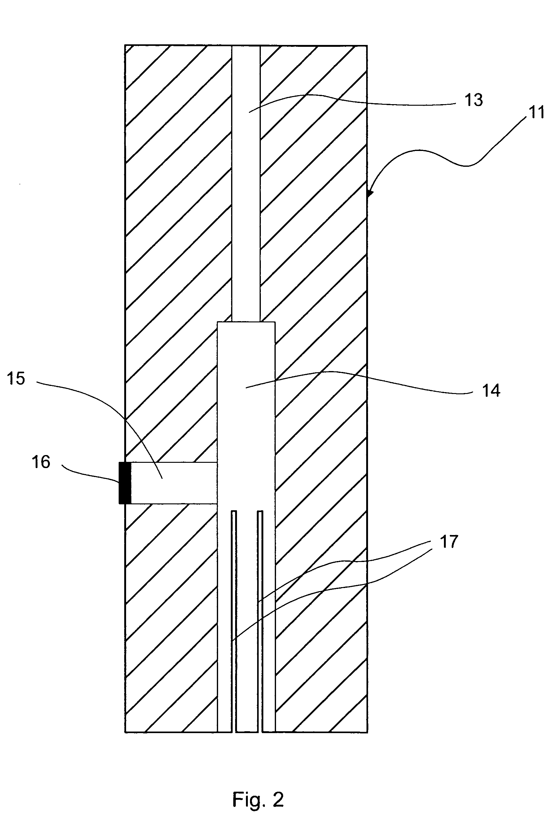
[0035] Peg 11 is shown in more detail in FIG. 2. The peg 11 is generally cylindrical in form, and has a stepped axial bore comprising a narrow upper bore 13 communicating with a wider lower bore 14. The bores 13, 14 are open at the upper and lower ends of the peg, respectfully. A radial bore 15 communicates with the lower bore 14, and has a stopper 16 removably inserted in its outer end.

[0036] The peg 11 is typically made of wood, but may alternatively ...


PUM


Abstract

A device (10) for detecting the presence of light averse insects, such as termites, is in the form of a peg (11) having a cavity (14) into which termites may enter when the peg is installed in the ground or other area where the presence of termites is to be detected. The cavity may include a termite bait. A light sensor (25) is located in the cavity, and has an output which is responsive to the detection of light. The light sensor operatively receives light from a light emitting device (LED) (23) only through a narrow passage extending through the peg from the LED (23) to the cavity (14). The passage is adapted to be at least partially blocked by the light averse insects to shield the cavity, and hence the light sensor means, from light from the passage. When the light sensor means (25) does not detect sufficient light, an electrical circuit (22) connected to the output of the light sensor means triggers an alarm light (26) to signal an alarm or alert condition.

Description

FIELD OF THE INVENTION [0001] This invention relates to an apparatus and method for detecting the presence of termites, and similar insects of the isoptera order which are averse to light. In particular, the invention is directed to an apparatus and method for electronically detecting termite activity using an optical sensor. BACKGROUND ART [0002] The dangers of termites (also known as “white ants”) are well known and documented. Termites can cause major damage to buildings in a relatively short time, and it is therefore important that property owners be vigilant in detecting the presence of termites. [0003] However, as termites live and nest underground or in concealed places, it is not normally possible to detect their presence visually. So-called “mud trails” on a surface may indicate the presence of termites, but these mud trails are normally constructed by termites in obscured places. Moreover, the absence of mud trails does guarantee that there is no termite infestation. Termi...

Claims


Application Information

Patent Timeline
IPC IPC(8): A01M1/02A01M1/20
CPCA01M1/026A01M2200/011A01M1/2011
Inventor LEWIS, MARK ROBERT
Owner LEWIS MARK ROBERT
Why Eureka
Try Eureka