Multiband planar antenna

Inactive Publication Date: 2005-09-01
THOMSON LICENSING SA
View PDF11 Cites 8 Cited by
  • Summary
  • Abstract
  • Description
  • Claims
  • Application Information

AI Technical Summary

Benefits of technology

[0006] The present invention proposes a passive solution making it possible t

Problems solved by technology

Within the framework of the deployment of wireless networks, the design of antennas is confronted with a particular problem due to the way in which the various frequencies are allocated to these networks.
It is apparent however that the use of a wideband antenna is not desirable for such coverage.
Specifically, in this case, the band covered is very large relative to the necessary band, presenting various drawbacks.
Thus, the use of a wideband antenna may encourage the degra

Method used


Image

  • Multiband planar antenna
  • Multiband planar antenna
  • Multiband planar antenna

Examples


Embodiment Construction

[0035] The present invention will be described while referring to an antenna of the annular slot type making it possible to ensure coverage of the standards at 2.4 GHz and at 5 GHz, namely, to cover the frequency bands allocated for the Hyperlan2 and IEEE802.11a standards. It is obvious to the person skilled in the art that the present invention may be applied to other types of standard and use an antenna made in a technology other than slot technology such as microstrip technology.

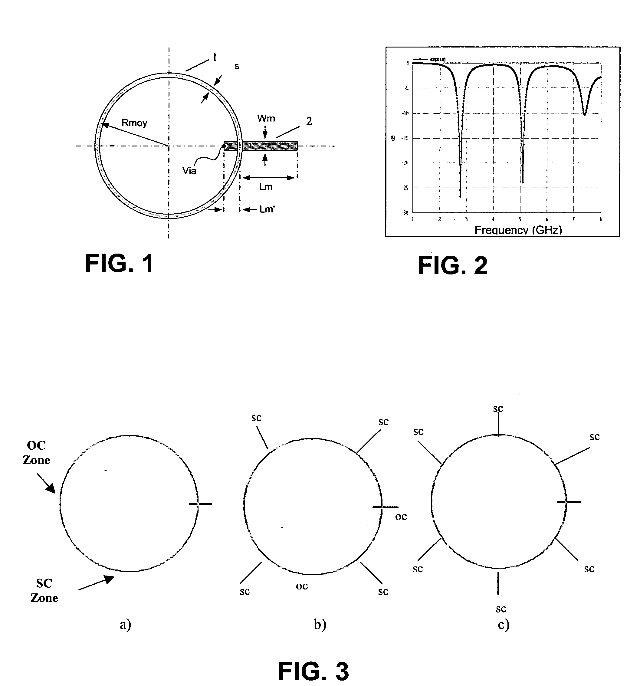
[0036] The structure and the manner of operation of a multiband planar antenna consisting of an annular slot fed by a feed line in microstrip technology, according to a line / slot transition, will firstly be described with reference to FIGS. 1 to 3.

[0037] As represented diagrammatically in FIG. 1, the antenna consists of a slot 1 made by etching a metallized substrate on its two faces. In the embodiment represented, the slot 1 forms a circle of mean radius Rmoy and of width Ws. On the substrate face oppo...


PUM


Abstract

The present invention relates to a multiband planar antenna consisting of at least one resonator formed of an element having a closed shape made on a substrate and dimensioned so as to operate in its fundamental mode at the resonant frequency of the lowest band. The resonator is fed by a feed line in such a way as to operate in all the higher modes. The resonator comprises means for modifying the resonant frequencies of the various modes in such a way as to cover the bands concerned.

Description

[0001] The present invention relates to a multiband planar antenna, and more particularly to a multiband planar antenna suited to wireless networks operating with distinct frequency bands. BACKGROUND OF THE INVENTION [0002] Within the framework of the deployment of wireless networks, the design of antennas is confronted with a particular problem due to the way in which the various frequencies are allocated to these networks. Thus, in the case of domestic wireless networks according to the IEEE802.1 b and IEEE802.11a standards, a frequency band at 2.4 GHz and two disjoint frequency bands around 5 GHz have been allocated for the deployment of wireless networks according to these standards. In this case, the spectrum to be covered is therefore composed of three disjoint sub-bands. The same phenomenon is encountered in respect of antennas that have to operate on two disjoint frequency bands such as GSM, GPRS, UMTS antennas, etc. [0003] Moreover, several standards currently exist for wir...

Claims


Application Information

Patent Timeline
IPC IPC(8): H01Q13/16H01Q5/00H01Q5/10H01Q5/357H01Q5/40H01Q9/04H01Q13/10
CPCH01Q5/00H01Q9/0464H01Q5/40H01Q5/357H01Q13/106E04B1/665E04B1/92
Inventor THUDOR, FRANCKBARON, FRANCOISLE BOLZER, FRANCOISE
Owner THOMSON LICENSING SA
Why Eureka
Try Eureka