Switching device and switching methods of the same

a technology of switching device and switch, which is applied in the direction of instruments, digital computers, computing, etc., can solve the problems of computer overloaded more or less, certain areas of manipulation, and inability to conduct switching with softwar

Inactive Publication Date: 2005-09-01
FUJITSU COMPONENENT LTD
View PDF9 Cites 36 Cited by
  • Summary
  • Abstract
  • Description
  • Claims
  • Application Information

AI Technical Summary

Benefits of technology

[0010] The present invention has been made in view of the above circumstances and has a general object of the present invention to provide a switching device and switching methods of the same. With the s

Problems solved by technology

Because, there is the problem in that it is impossible to conduct the switching with software, when the computer is off or while an operating system (OS) is being started or ended.
There is a problem in that a certain area for

Method used


Image

  • Switching device and switching methods of the same
  • Switching device and switching methods of the same
  • Switching device and switching methods of the same

Examples


first embodiment

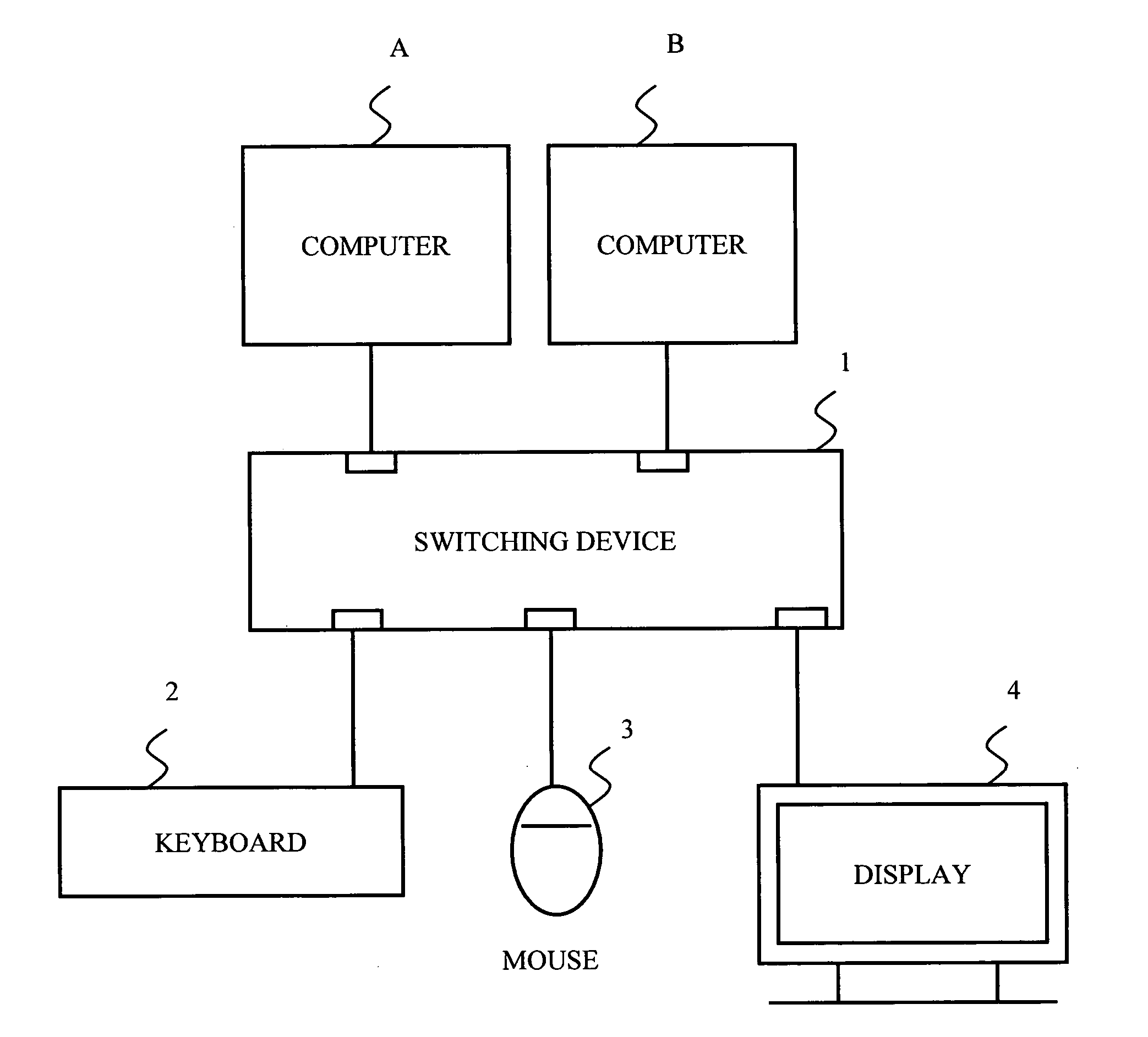
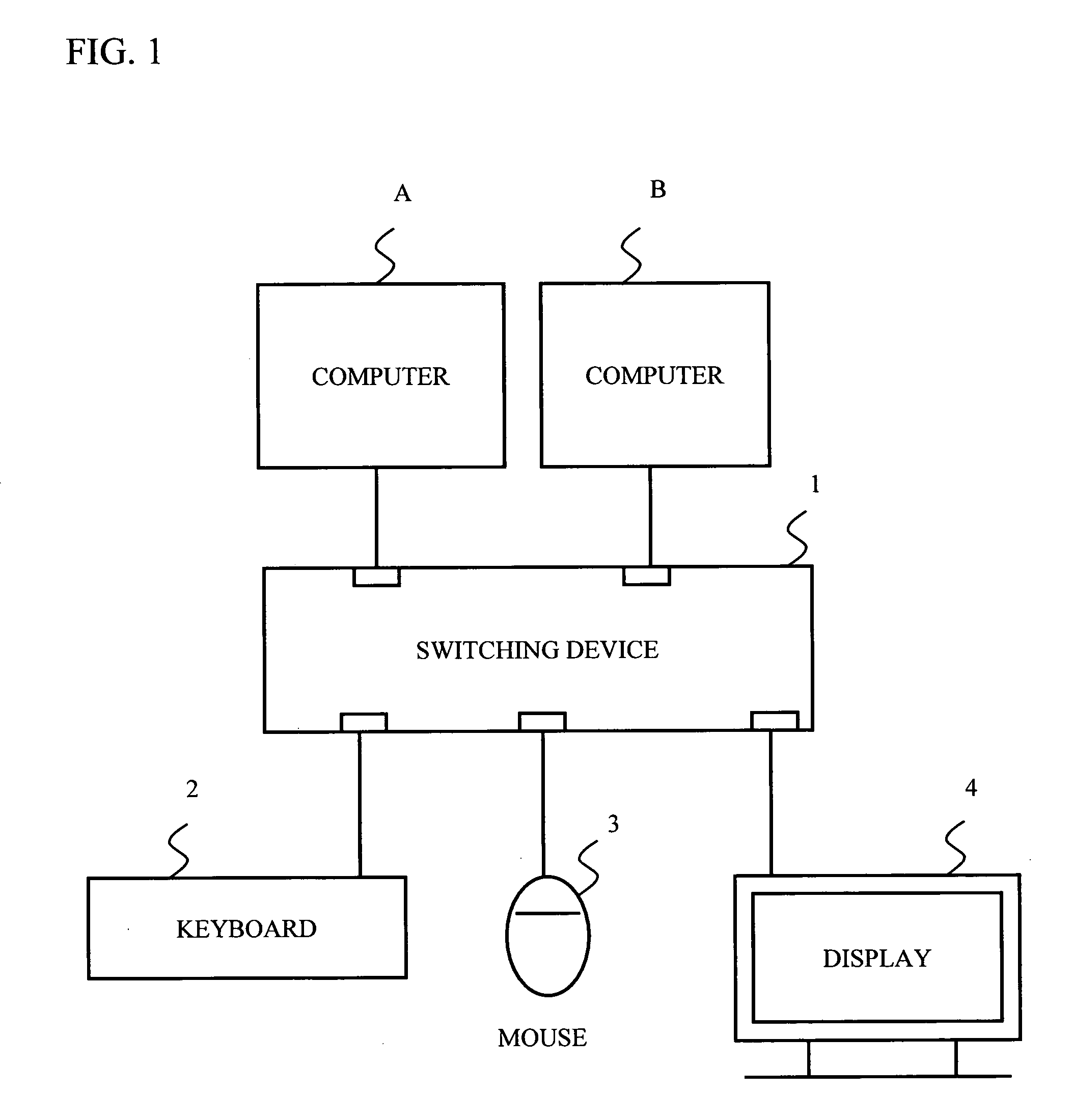
[0044]FIG. 1 shows a connection example of a switching device in accordance with a first embodiment of the present invention. Referring to FIG. 1, computers A and B, a keyboard 2 and a mouse 3 for manipulation, and a display 4 are connected to the switching device 1 via given connection terminals. The switching device 1 selects the computer to be operated from multiple computers, and selectively changes to the computer to be operated. An operator is able to operate the computers A and B, while watching the display 4 and switching between the computers A and B, with the use of a set of the mouse 3 and the keyboard 2.

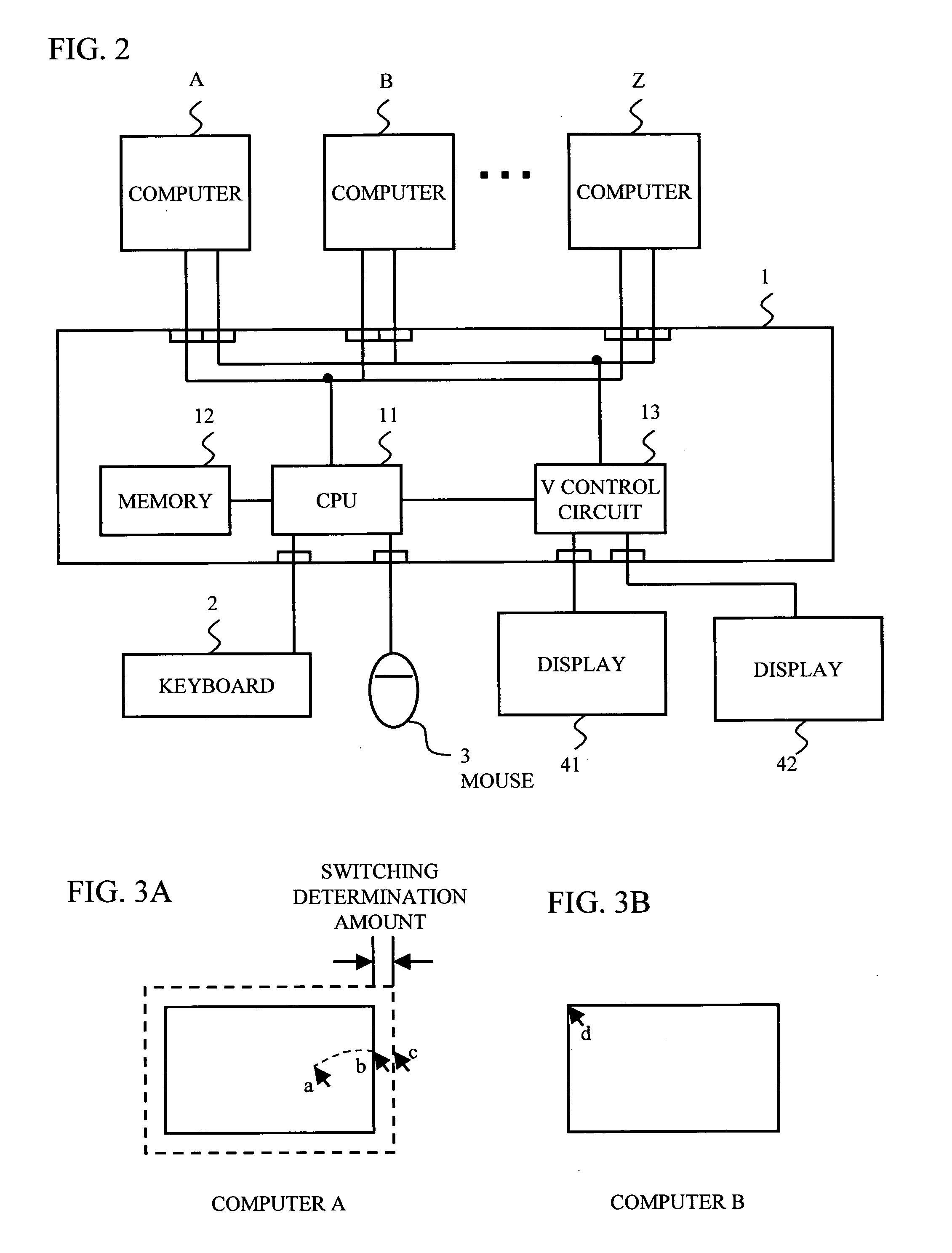
[0045]FIG. 2 shows a block diagram of the switching device and another connection example of the switching device. Referring to FIG. 2, multiple computers, that is, at least two computers are connected to the switching device 1, and two displays are connected, too. As shown in FIG. 2, the switching device 1 includes a CPU 11, a memory 12, and a V control circuit 13. Also...

second embodiment

[0055] Next, a description will be given of a second embodiment of the present invention. The switching device in accordance with the second embodiment of the present invention has the same configuration as that of the first embodiment of the present invention. Therefore, a description will be given with FIG. 2. FIG. 5 shows a switching operation of the switching device so as to selectively change the computer to be operated in accordance with the second embodiment of the present invention. FIG. 5A illustrates a position of a mouse cursor before switching. FIG. 5B illustrates a position of the mouse cursor after switching. In the case where the resolution is uncertain since the resolution cannot be acquired from the video signals, a predicted resolution that is sufficiently greater than the real resolution, for example, QXGA (Quad XGA (extended Graphics Array)) is assumed as shown in FIG. 5.

[0056] In the case where the CPU 11 detects that the mouse cursor moves from a home position...

third embodiment

[0058] Next, a description will be given of the switching device in accordance with a third embodiment of the present invention. In accordance with the third embodiment of the present invention, the relative coordinate data is converted into absolute coordinate data. The absolute coordinate data is used for displaying the mouse cursor, and the relative coordinates are used for selectively changing the computer. The switching device in accordance with the third embodiment of the present invention has the same configuration as that of the first embodiment of the present invention. Therefore, a description will be given with FIG. 2.

[0059]FIG. 6 is a flowchart describing an operation of the switching device in accordance with the third embodiment of the present invention. A description will be given on the assumption that the switching device 1 selects the computer A as the computer to be operated. In step S201, the V control circuit 13 acquires the resolution from the video signals of...


PUM


Abstract

A switching device that selectively changes a computer to be operated from multiple computers including a control unit that the control unit detects a cursor position on the computer to be operated based on coordinate data and a computer resolution of the computer to be operated, the coordinate data being generated by performing a same acceleration process as the computer to be operated, on relative coordinate data that has been acquired from a given pointing device, and the control unit selectively changing changes the computer to be operated according to the cursor position. It is thus possible to selectively change the computer to be operated without any dedicated software or requiring a given space for manipulation.

Description

BACKGROUND OF THE INVENTION [0001] 1. Field of the Invention [0002] This invention generally relates to a switching device and switching methods of the same. [0003] 2. Description of the Related Art [0004] Conventionally, the switching devices have been proposed to control multiple computers with a set of keyboard, mouse, and display, or a set of keyboard, mouse, and multiple displays. With the above-mentioned switching device, a switching key or a hot key was used in the case where the switching was performed with hardware. Because, there is the problem in that it is impossible to conduct the switching with software, when the computer is off or while an operating system (OS) is being started or ended. Conventional techniques have been proposed as follows so as to solve the aforementioned problem. [0005] A switching device described in Japanese Patent Application Publication No. 11-31064 (hereinafter referred to as Document 1) is equipped with a storage unit that stores common coord...

Claims


Application Information

Patent Timeline
IPC IPC(8): G06F3/023G06F3/00G06F3/038G09G5/00
CPCG06F3/038G06F3/023
Inventor FUJITA, KENICHI
Owner FUJITSU COMPONENENT LTD
Why Eureka
Try Eureka