Portable data unit

Inactive Publication Date: 2005-09-01
HITACHI LTD
View PDF12 Cites 150 Cited by
  • Summary
  • Abstract
  • Description
  • Claims
  • Application Information

AI Technical Summary

Benefits of technology

[0007] Accordingly, one object of the present invention is to provide a slide type portable data unit i

Problems solved by technology

In the above-mentioned conventional example, the thin two casings are slidably coupled to each other, there has been such a severe task that components are appropriately arranged in these casings.
That is, for example, should the interior components be not efficiently arranged, the configuration would become large-sized, resulting in deterioration of portability.
In particular, the higher the optical telescopic function, the larger the size of the cameral mechanism portio

Method used


Image

  • Portable data unit
  • Portable data unit
  • Portable data unit

Examples


first embodiment

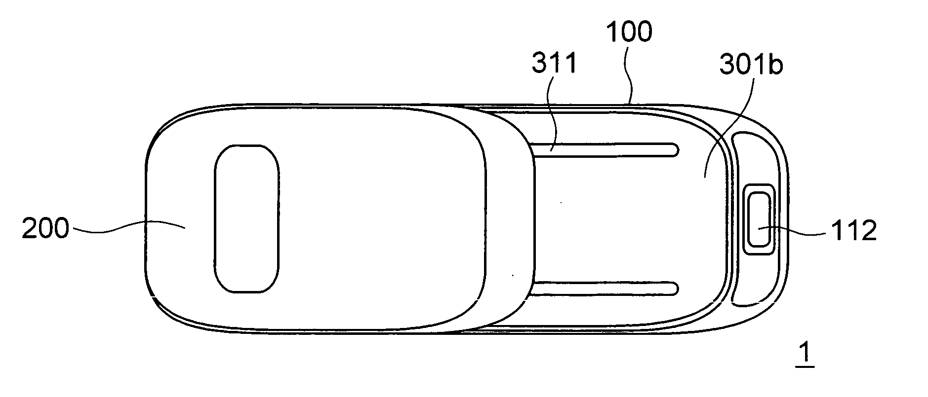
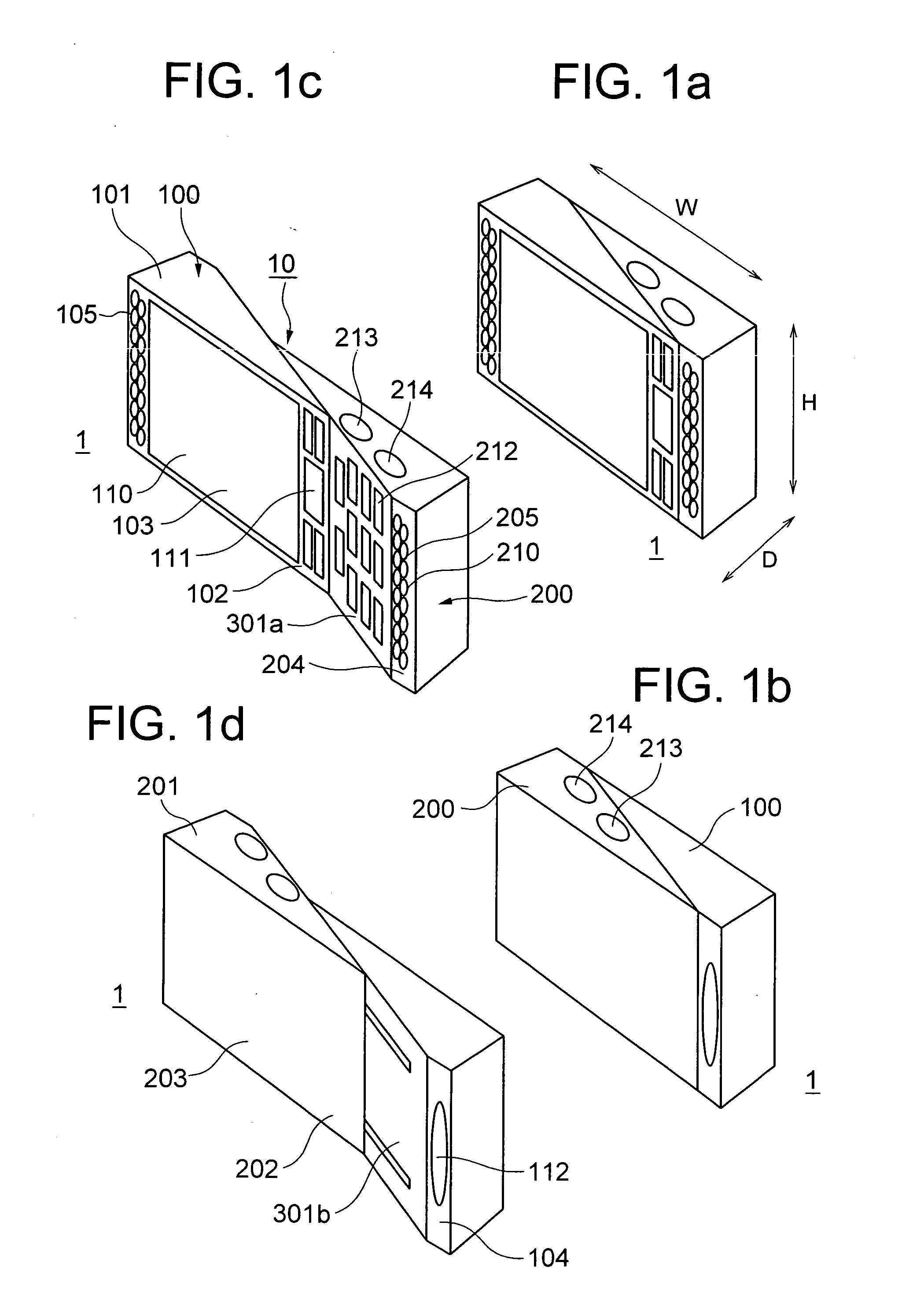
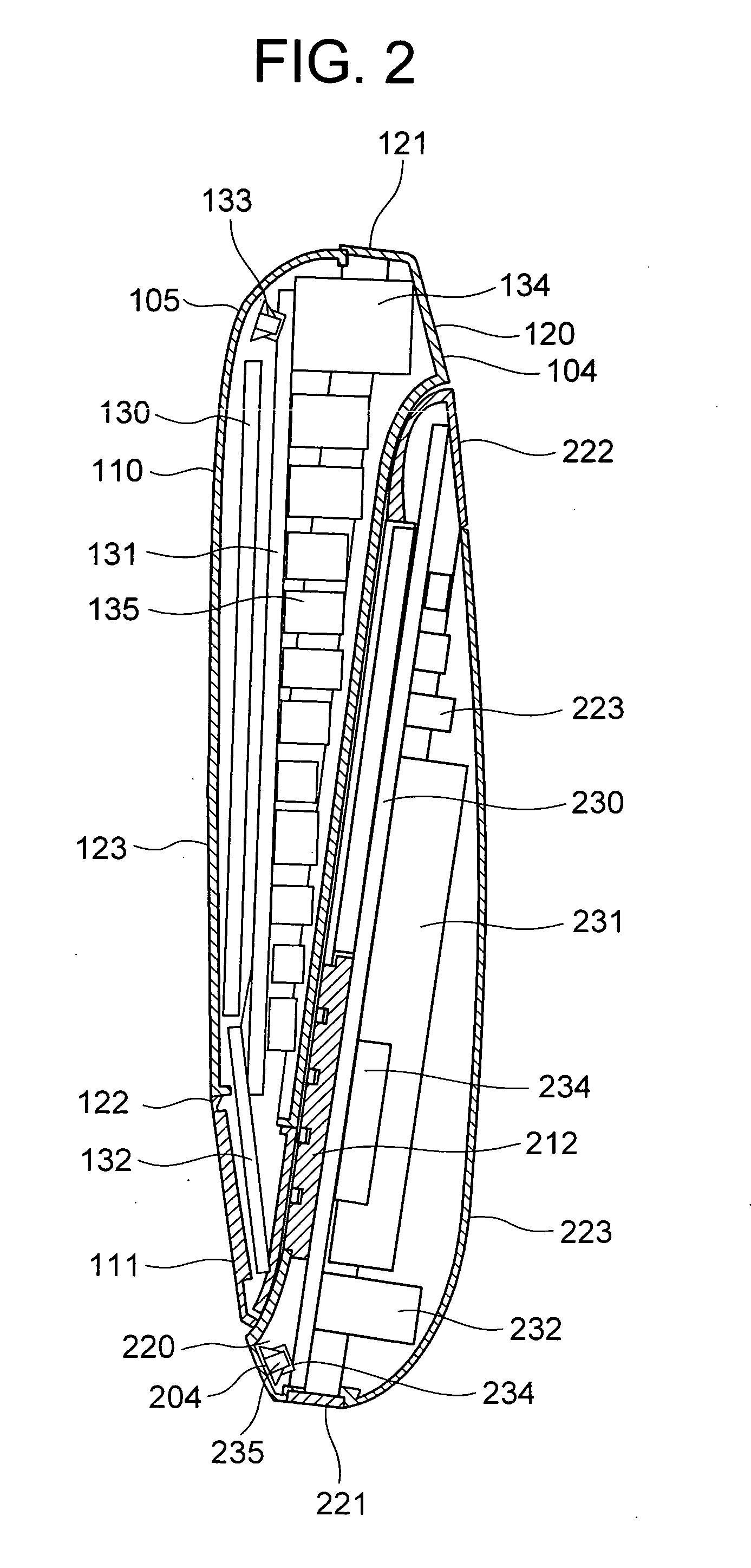
[0035]FIGS. 1a to 7b show a portable data unit (mobile telephone) in a first embodiment of the present invention, among which FIGS. 1a to 1d are external views illustrating the portable data unit in various conditions, FIG. 2 is a sectional view illustrating the mobile telephone, FIGS. 3a to 3d are external views illustrating the mobile telephone having its casings which are retracted to each other, FIGS. 4a to 4c are external views illustrating the mobile telephone having its casings which are extended from each other, FIG. 5 is a sectional view illustrating a slide mechanism, FIG. 6 is a view for explaining a holding posture in a condition in which the casings are extended from each other, and FIGS. 7a to 7b are views for explaining a posture for image pick-up by a camera.

[0036] At first, explanation will be made of the mobile telephone in the first embodiment with reference to FIGS. 1a to 1d among which FIGS. 1a and 2b are perspective views illustrating the mobile telephone in a...

second embodiment

[0082]FIGS. 8a to 8b are external views which show a portable data unit (mobile telephone) in a second embodiment of the present invention, among which FIG. 8a is a perspective view illustrating the mobile telephone as viewed from the front surface side in the second condition, FIG. 8b is a perspective view illustrating the mobile telephone as viewed from the front side in the first condition, and FIG. 8c is a perspective view illustrating the mobile telephone as viewed from the rear surface side in the first condition.

[0083] Referring to FIG. 8a to 8c, the mobile telephone which is generally denoted by 2, incorporates a first casing 100, a second casing 200 and a slide mechanism portion 300 through which these two casings are slidably connected. In this configuration, the housing 10 consisting of these two casings is basically in the form of a thin flattened parallelepiped body so as to have its height H greater than its depth D and its width W greater than its height H. The upper...

third embodiment

[0092] Next, explanation will be made of a mobile telephone in a third embodiment of the present invention with reference to FIGS. 9a to 14 among which FIGS. 9a to 9b are conceptual views illustrating the mobile telephone, FIG. 10a to FIG. 11b are external views illustrating the mobile telephone in a first condition, FIGS. 12a to 12c are external views illustrating the mobile telephone in a second condition, and FIG. 13 to FIG. 14c are sectional views illustrating an internal configuration of the mobile telephone. It is noted that like reference numerals denote like parts and directions to those in the afore-mentioned embodiments in order to abbreviate double explanation.

[0093] Explanation will be made of the general configuration of this embodiment with reference to FIGS. 9a to 9b which show a conceptual configuration of the mobile telephone 5 which is used with its longitudinal direction being set up and down in a fundamental posture, and which mainly has a communication function...


PUM


Abstract

A slide type portable data unit which has satisfactory interior mounting efficiency, having a first casing, a second casing and a slide mechanism portion connecting the first casing and the second casing so that the two casings are slidable in one direction, wherein the slide mechanism portion connects the first casing and the second casing so that the first casing and the second casing have a fore-and-aft relationship, and are taken in a first condition in which the second casing is superposed with the first casing, and in a second condition in which the two casings are displaced from each other in the one direction, and the first casing has one end part, in the one direction, which is not superposed with the second casing in the first condition, and a camera portion is incorporated in this part which is not superposed.

Description

CLAIM OF PRIORITY [0001] The present application claims priority from Japanese application JP 2004-052702 filed on Feb. 27, 2004, the content of which is hereby incorporated by reference into this application. BACKGROUND OF THE INVENTION [0002] The present invention relates to a slide type portable data unit composed of a plurality of casings which are slidably connected to one another so that the portable data unit can have a compact configuration when the casings are retracted into one another, but have a length adjusted to an ear and a mouth of a user when they are extended from one another. [0003] These years, mobile telephones incorporating a camera function, have been prosperously used. Most of these mobile phones have such a deformable configuration that it is compact during carrying by a user but it has a length adjusted to an ear and the mouth of the user during telephone conversation. Most of these conventional examples have been a foldable type, that is, two casings are f...

Claims


Application Information

Patent Timeline
IPC IPC(8): H04M1/02H04M1/21H04N5/225H04N5/232H04N5/64H05K7/18
CPCH04M1/0237H04M2250/52H04N2007/145H04N5/23293H04N5/64H04N5/2251H04N23/531H04N23/631
Inventor KOTA, YUICHIROIKEDA, MINORU
Owner HITACHI LTD
Why Eureka
Try Eureka