
Safe lock with motor controlled bolts and electronic access

a technology of electronic access and safe locks, applied in the field of safe lock systems, can solve the problems of cumbersome methods, time-consuming, and unattractive looking safe locks, and achieve the effect of improving the locking and unlocking of the door

Inactive Publication Date: 2005-09-08
TRITEQ LOCK & SECURITY L L C
View PDF77 Cites 29 Cited by
  • Summary
  • Abstract
  • Description
  • Claims
  • Application Information

AI Technical Summary

Benefits of technology

[0006] The first object is to improve the locking and unlocking of the door by removing the need for a handle and a lock-box with a bolt.
[0007] The second object is to replace manual movement of the locking bolts with motor control movement of the lock bolts. The third object is to provide a less user interactive procedure and an easier interface to access and lock the safe.
[0008] The forth object is to provide a faster method for accessing and locking the safe.
[0009] The fifth object is to improve the security of the door and remove the point of attack by removing the need for an access control unit (keypad or dial) from the door and replace with a remote or removable keypad transmission device.

Problems solved by technology

These methods are typically cumbersome and time consuming.
In addition, a safe as described above will typically have an unattractive looking handle and dial or keypad lock mounted to the exterior of the door.

Method used


Image

  • Safe lock with motor controlled bolts and electronic access
  • Safe lock with motor controlled bolts and electronic access
  • Safe lock with motor controlled bolts and electronic access

Examples


Embodiment Construction

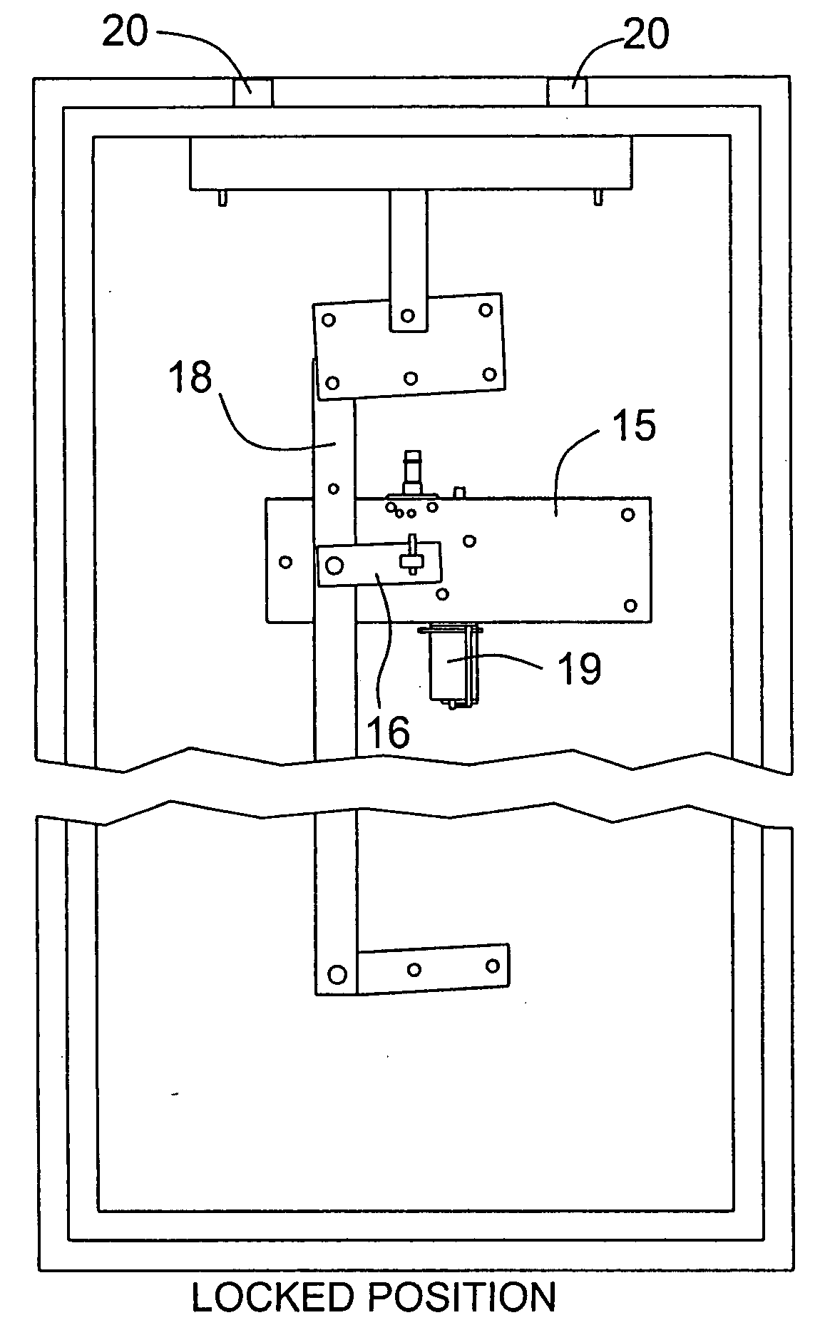
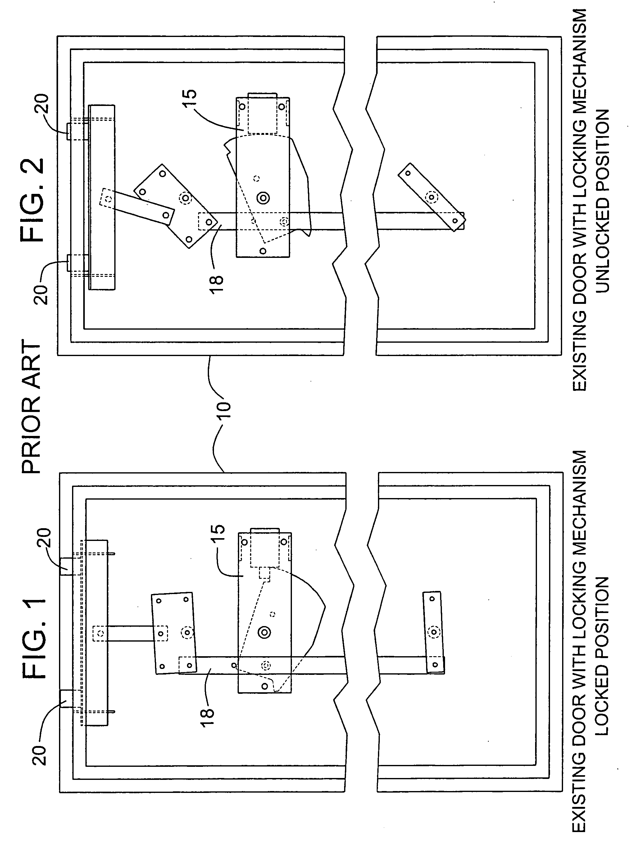
[0023] The prior art is illustrated in FIGS. 1 and 2. It would typically consist of rotatable exterior handle, shaft for said handle that passes thru the door (not shown), a pawl or cam device mounted in the interior space on the shaft, a mechanical “lock box”15 that houses a mechanism that interfaces 18 with a exterior dial or key pad to allow a ‘bolt’20 to interact with the above pawl or cam in manner as to prevent rotation.

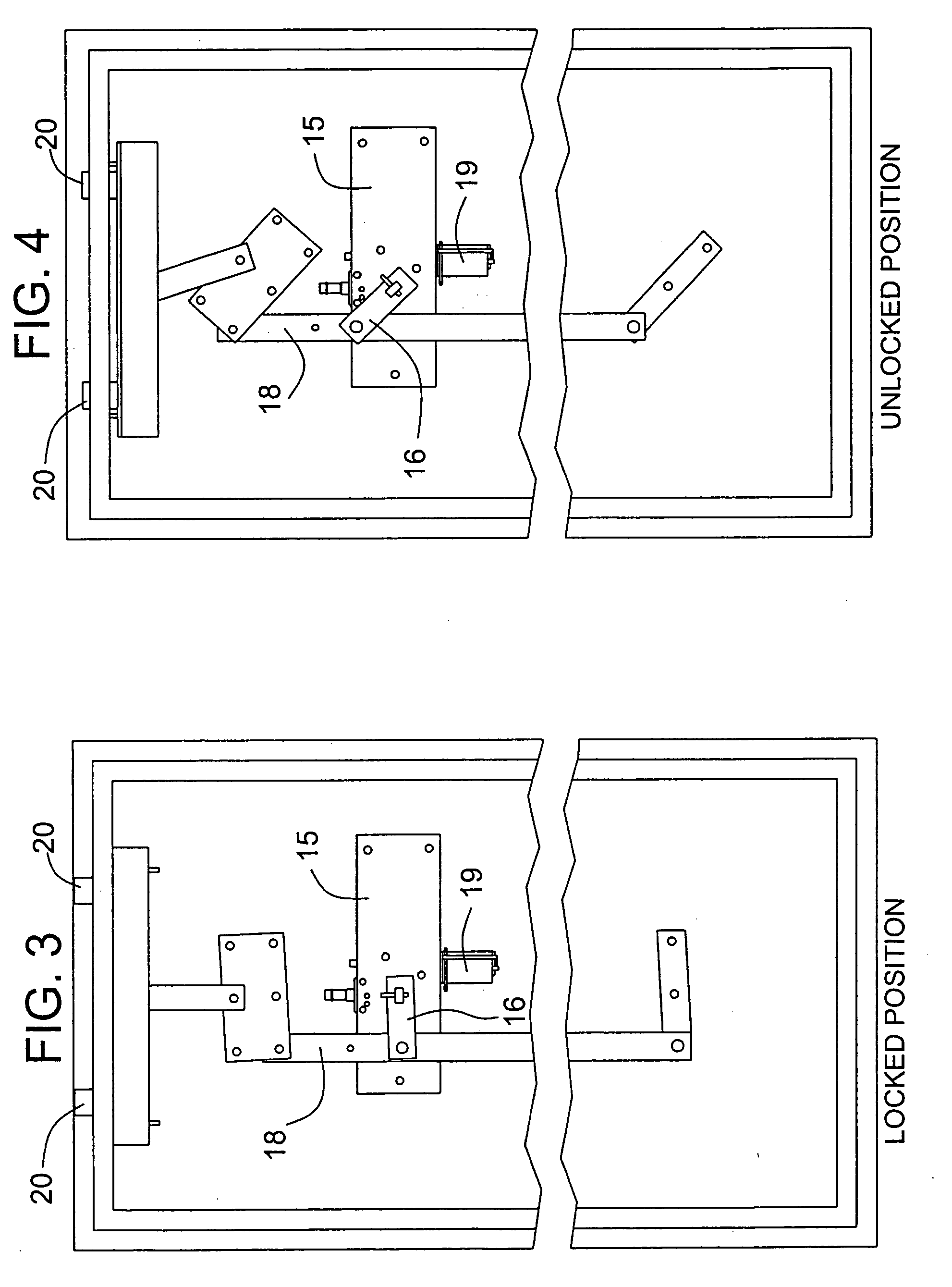
[0024] This invention consists primarily of a motor controlled mechanism to control the movement of the lock bolts in the safe door, an electronic control interface to the motor mechanism, an access control device, and a power source.

[0025] The motor control mechanism is best shown in FIGS. 5, 6 and 7. It serves to eliminate the handle drive system in safes, as they exist today. The motorized lock provides a motor 19 to gear reduction system 17 that allows adequate power to control and move the mechanism, and also will hold back several hundreds of pounds of ...


PUM


Abstract

An enhanced bolt control system for safes and the like utilizes a reversible motor and worm gear drive that operates the deadbolt linkage. An electronic control with a microcomputer interface drives the motor control and the system may be operated by a keypad or a remote wireless control device.

Description

FIELD OF THE INVENTION [0001] The present invention relates generally to safe lock systems that control the movement of the deadbolts such as in a conventional security safe. More specifically the invention provides an enhanced bolt control, and it may also incorporate a unique access control device such as a keypad access control and / or a remote control device that transmits codes in a wireless medium. [0002] This application claims priority from provisional application Ser. No. 60 / 550,801, filed Mar. 5, 2004 and incorporates herein by reference. BACKGROUND OF THE INVENTION [0003] Safes today are typically secured with a mechanism comprising of deadbolts or the like in the door, which generally extend into the cabinet frame when locked, the motion going from unlocked to locked is typically controlled by a rotate-able exterior mounted handle controlled by a mechanical controlled or electronic controlled lock-box mechanism. The handle is prevented from rotating by a mechanism that is...

Claims


Application Information

Patent Timeline
IPC IPC(8): E05B49/00E05G1/04
CPCE05B47/0012E05B65/0075E05G1/04E05B2047/0052E05B2047/0094E05B2047/002
Inventor DENISON, WILLIAM D.MYERS, GARY L.ROATIS, CALIN V.PAETH, RICHARDCAPTARENCU, CATALIN
Owner TRITEQ LOCK & SECURITY L L C
Learn More