
Vending machine lock with motor controlled slide-bar and hook mechanism and electronic access

Active Publication Date: 2006-08-17
TRITEQ LOCK & SECURITY L L C
View PDF93 Cites 9 Cited by
  • Summary
  • Abstract
  • Description
  • Claims
  • Application Information

AI Technical Summary

Benefits of technology

[0006] The first object is to improve the locking and unlocking of the door by removing the need for a handle interfaced to a slide-bar hook mechanism.
[0008] The third object is to provide a less user interactive procedure and an easier interface to access and lock the vending machine.
[0010] The fifth object is to improve the security of the door and remove the point of attack by removing the need for an access control unit (T-handle and lock core) from the door and replace with an electronic remote or removable keypad transmission device.

Problems solved by technology

These methods are typically cumbersome and time consuming.
In addition, an enclosure as described above will typically have an unattractive looking handle and dial or keypad lock mounted to the exterior of the door.

Method used


Image

  • Vending machine lock with motor controlled slide-bar and hook mechanism and electronic access
  • Vending machine lock with motor controlled slide-bar and hook mechanism and electronic access
  • Vending machine lock with motor controlled slide-bar and hook mechanism and electronic access

Examples


Embodiment Construction

[0024] The prior art is illustrated in U.S. Pat. No. 4,993,247. It would typically consist of a T-handle, a slide-bar mechanism, and the interface of these components. Electronic locking systems are shown in Roatis et al. U.S. Pat. Nos. 6,581,986 and 6,575,504, for example, as used with ordinary lighted doors used on vending machines. Glass front doors can use a locking system similar to a school locker wherein a sliding bar having slots or hooks engage with complimentary slots or hooks.

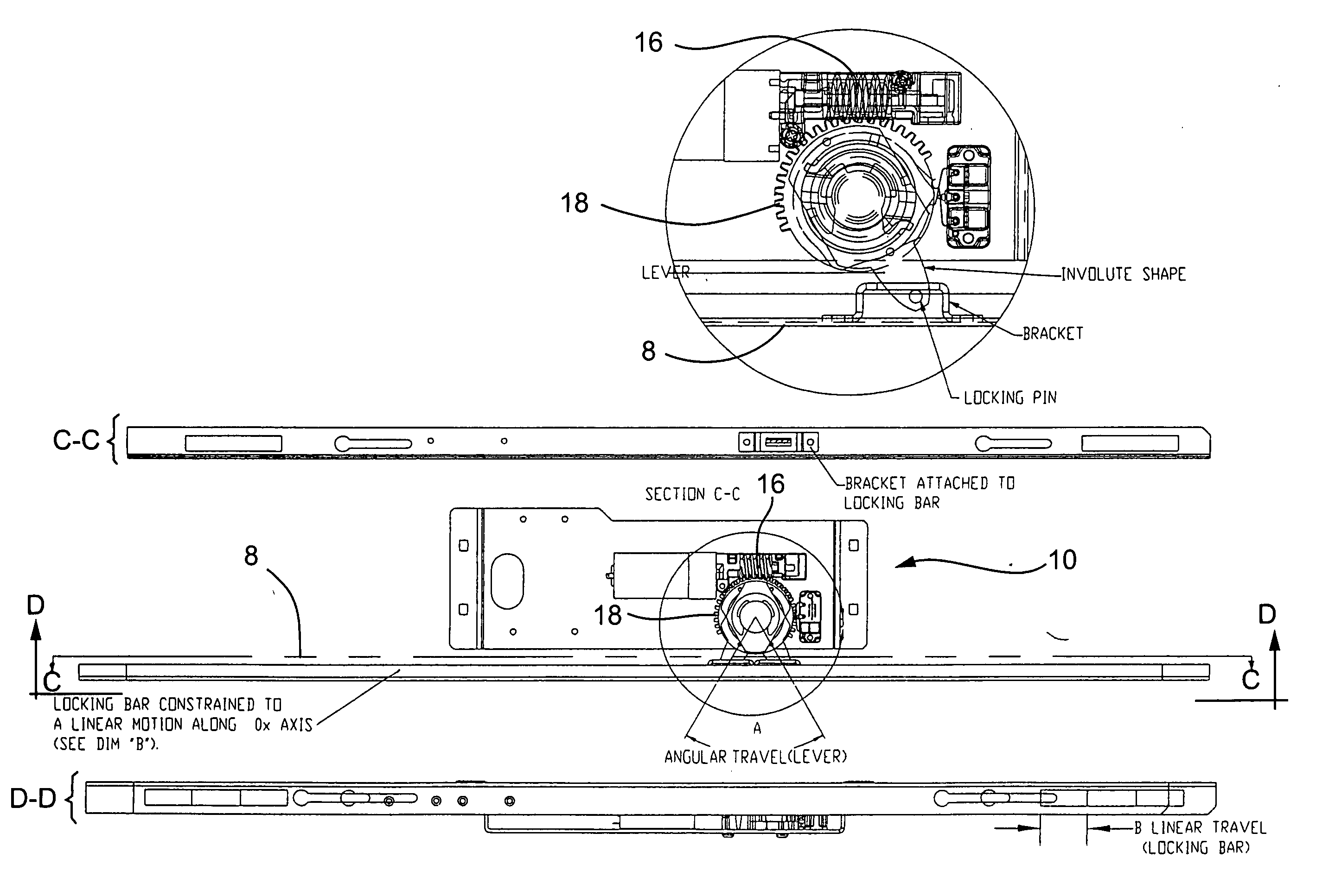
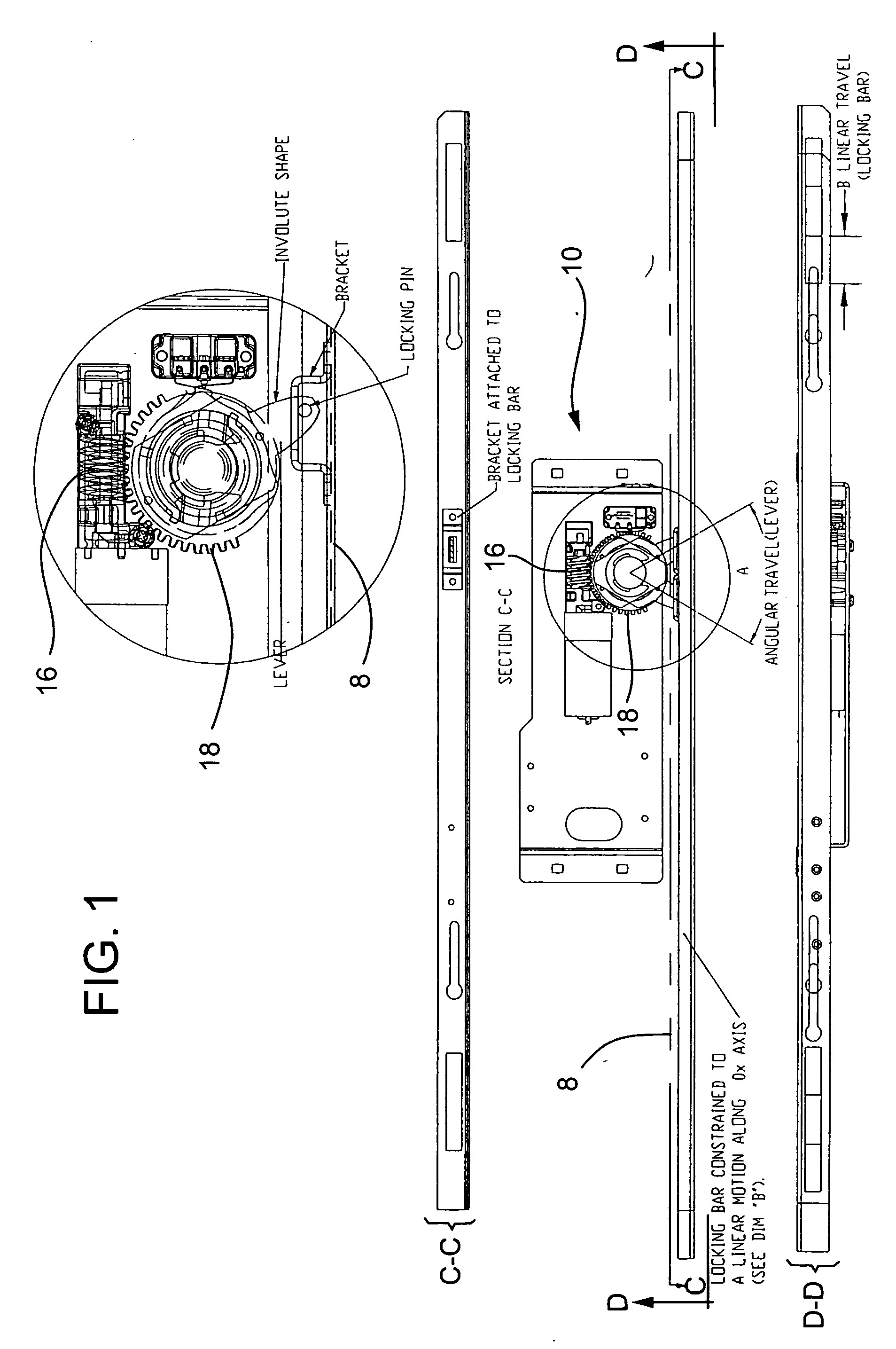
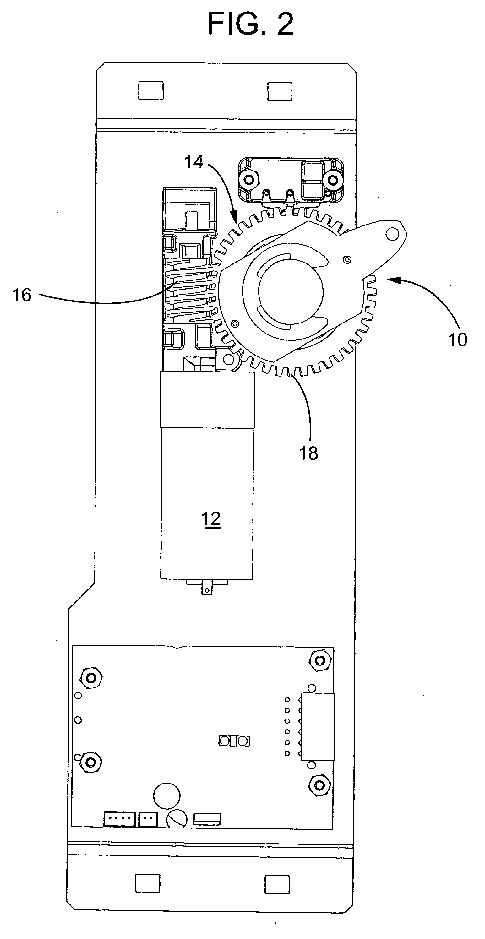
[0025] This invention consists primarily of a motor controlled mechanism to control the movement of the slide-bar mechanism 8 in a vending machine or the like; an electronic control interface to the motor mechanism, an access control device, and a power source.

[0026] The motor controlled mechanism 10 is shown in drawing FIGS. 1, 2, 3, 3A and 3B. It serves to eliminate the handle drive system in vending machines, as they exist today. The motorized lock 10 provides a motor 12 to gear reduction 14 sys...


PUM


Abstract

An enhanced slide and hook locking mechanism control system for vending machines and the like that utilizes a reversible motor and worm gear drive that operates the slide and hook mechanism. The worm drive is coupled to the slide through a crankshaft type of interconnection. Or as alternatives, the slide means can be gear driven or it may be connected using push-pull type of cable or rod. An electronic control with a microcomputer interface drives the motor control and the system may be operated by a keypad or a remote wireless control device.

Description

RELATED APPLICATIONS [0001] This application claims priority to U.S. Provisional Application No. 60 / 618,069, filed Oct. 12, 2004, and incorporates the same by reference in its entirety. It is also related to U.S. Provisional Application No. 60 / 550,801, filed Mar. 5, 2004, now application Ser. No. 11 / 073,184, filed Mar. 3, 2005.FIELD OF THE INVENTION [0002] The present invention relates generally to vending machine lock systems that control the movement of the slide and hook mechanism such as in a conventional snack food or glass-front vending machine. More specifically the invention provides an enhanced slide mechanism control, and it may also incorporate a unique access control device such as a keypad access control and / or a remote control device that transmits codes in a wireless medium. BACKGROUND OF THE INVENTION [0003] Snack food and glass-front vending machines today are typically secured with a mechanism comprising of a slide-bar and hooks or the like in the door, which gener...

Claims


Application Information

Patent Timeline
IPC IPC(8): E05B65/00
CPCE05B47/0012G07F5/26E05B47/026Y10T70/5093Y10T70/5978Y10T70/7113Y10T292/1021Y10T292/1079
Inventor DENISON, WILLIAM D.MYERS, GARY L.PAETH, RICHARDCAPTARENCU, CATALINROATIS, CALIN V.
Owner TRITEQ LOCK & SECURITY L L C
Learn More