
Carry-on baggage container with a folding chair

Inactive Publication Date: 2005-09-08
SHEN TAI IND
View PDF7 Cites 12 Cited by
  • Summary
  • Abstract
  • Description
  • Claims
  • Application Information

AI Technical Summary

Benefits of technology

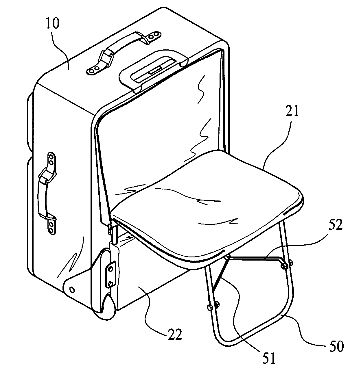
[0005] A primary object of the present invention is to provide a carry-on baggage container with a folding chair, so that a traveler may pivotally turn the folding chair relative to the baggage container to an extended position for use conveniently.
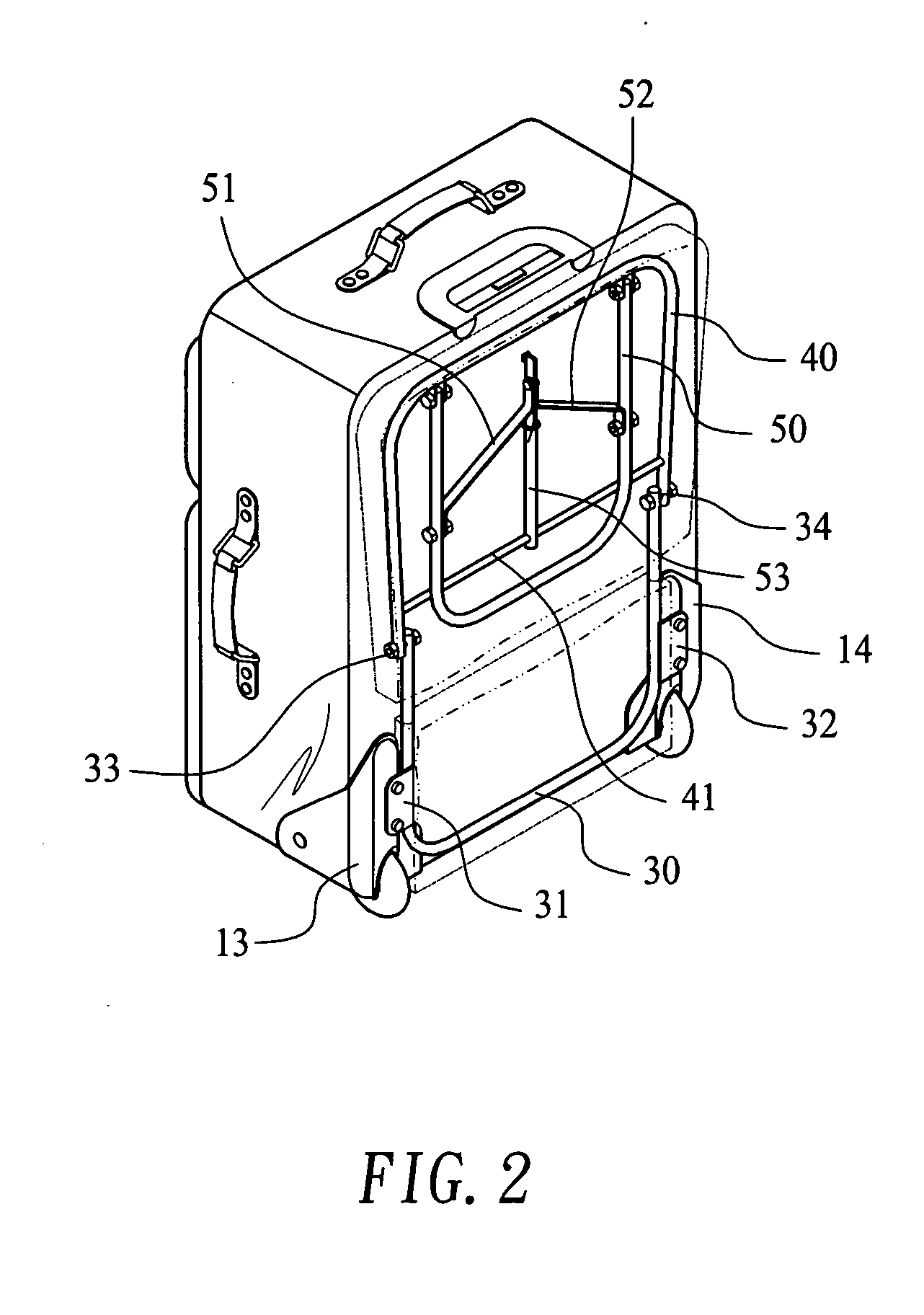
[0006] To achieve the above and other objects, the carry-on baggage container of the present invention is provided on one surface with a folding chair, which includes a base portion fixedly attached to the container surface, a seat portion pivotally connected at an end to a top of the base portion, and a leg portion pivotally connected at an upper end to a front crossbar of the seat portion. The leg portion includes two slant stays pivotally connected at outer ends to two lateral sides of the leg portion and at inner ends to a first end of a central bar, of which a second end is pivotally connected to a rear crossbar of the seat portion. The folding chair is normally in a folded position flatly attached to the surface of the baggage container and can be readily turned to an extended position for use.

Problems solved by technology

These carry-on baggage containers are normally very heavy with various kinds of articles loaded therein.
Even if the currently available carry-on baggage containers are equipped with wheels and can be effortlessly moved around, they are still a burden to the traveler, particular a traveler on a long-distant trip or a transit passenger, who is very tired at the end of the travel, and hardly has strength to handle the carry-on baggage.
Frequently, a traveler also has to wait for boarding in the waiting room for a considerably long time, particularly at an airport that executes strict passenger inspection and requires passengers to check in as early as possible.
And, it is apparent an unpleasant experience to wait in a crowded waiting room and can hardly find a seat to take a rest.

Method used


Image

  • Carry-on baggage container with a folding chair
  • Carry-on baggage container with a folding chair
  • Carry-on baggage container with a folding chair

Examples


Embodiment Construction

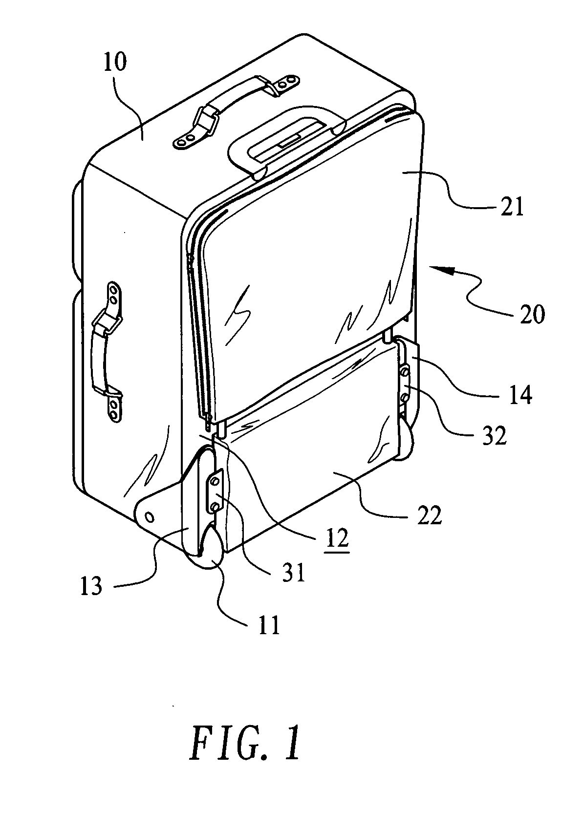
[0018] Please refer to FIG. 1 that is a perspective view of a carry-on baggage container 10 with a folding chair 20 according to a preferred embodiment of the present invention. The carry-on baggage container 10 is a traveling case or trunk provided with wheels 11 and can therefore be easily pulled by and carried along with a user. In the present invention, the carry-on baggage container 10 is provided at one surface 12 (it is a rear surface of the baggage container 10 in the illustrated embodiment) with a folding chair 20, which is normally folded to flatly attach to the rear surface 12 of the baggage container 10. That is, when the folding chair 20 is not in use, it is in a folded position flatly bearing against the rear surface 12. In the illustrated embodiment, different parts of the folding chair 20 are received in covers 21, 22 that are provided with zippers or other functionally equivalent fastening means, so that the zippers may be pulled to open the covers 21, 22 by predete...


PUM


Abstract

A carry-on baggage container is provided on one surface with a folding chair, which includes a base portion fixedly attached to the baggage container surface, a seat portion pivotally connected at a rear end to a top of the base portion, and a leg portion pivotally connected at an upper end to a front crossbar of the seat portion. The leg portion includes two slant stays pivotally connected at outer ends to two lateral sides of the leg portion and at flat and bent inner ends to a flat section at a first end of a central bar, of which a second end is pivotally connected to a rear crossbar of the seat portion. The folding chair is normally in a folded position flatly attached to the baggage container and can be readily turned to an extended position for use.

Description

FIELD OF THE INVENTION [0001] The present invention relates to a carry-on baggage container with a folding chair, and more particularly to a carry-on bag or trunk provided with a folding chair that may be pivotally turned relative to the bag or trunk to an extended position for use at any time at any place. BACKGROUND OF THE INVENTION [0002] A traveler, either a tourist or a businessman, would usually have one or more containers, such as trunks, knapsacks or bags, for carry-on baggage. These carry-on baggage containers are normally very heavy with various kinds of articles loaded therein. Many currently available carry-on baggage containers are equipped with wheels to allow easy movement of them effortlessly. [0003] Even if the currently available carry-on baggage containers are equipped with wheels and can be effortlessly moved around, they are still a burden to the traveler, particular a traveler on a long-distant trip or a transit passenger, who is very tired at the end of the tr...

Claims


Application Information

Patent Timeline
IPC IPC(8): A47C13/00A47D1/02
CPCA45C5/14A45C2009/002A45C9/00
Inventor WANG, TENG YIWU, CHANG I.
Owner SHEN TAI IND
Learn More