Gas bag module, in particular for a knee gas bag

Inactive Publication Date: 2005-09-08
TRW AUTOMOTIVE GMBH
View PDF16 Cites 35 Cited by
  • Summary
  • Abstract
  • Description
  • Claims
  • Application Information

AI Technical Summary

Benefits of technology

[0008] The gas bag module according to the invention includes a housing, a gas generator and a gas bag. The gas generator and the gas bag form a unit which is floatingly mounted in the interior of the housing. The gas bag module according to the invention is distinguished in that no complicated tolerance adjustment is required. The housing is installed in the instrument carrier. The gas generator and the gas bag attached thereto may be fitted to a carrier associat

Problems solved by technology

The disadvantage of both solutions is that they require a large space, are very heavy and their assembly is complicated.
Particularly critic

Method used


Image

  • Gas bag module, in particular for a knee gas bag
  • Gas bag module, in particular for a knee gas bag
  • Gas bag module, in particular for a knee gas bag

Examples


Embodiment Construction

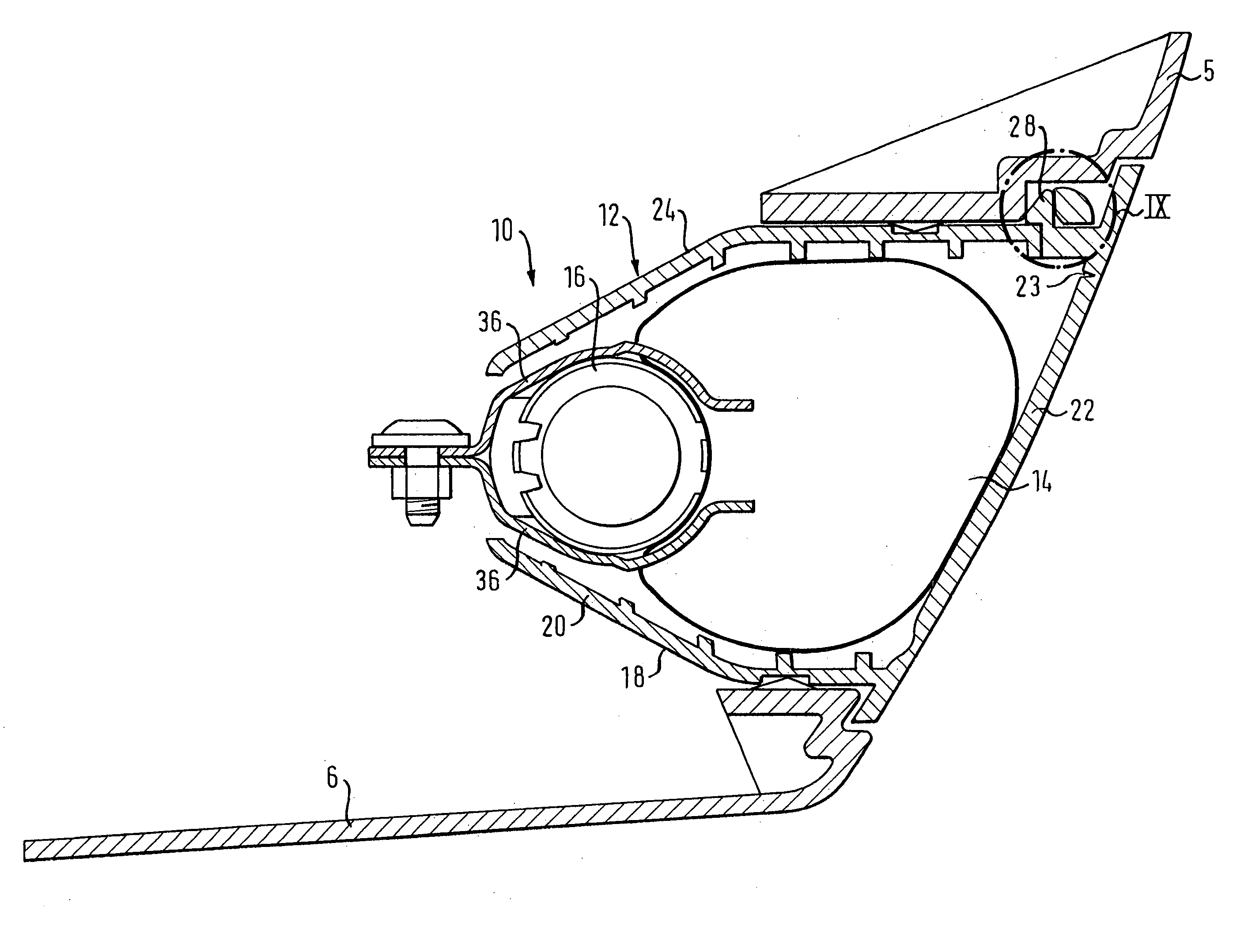
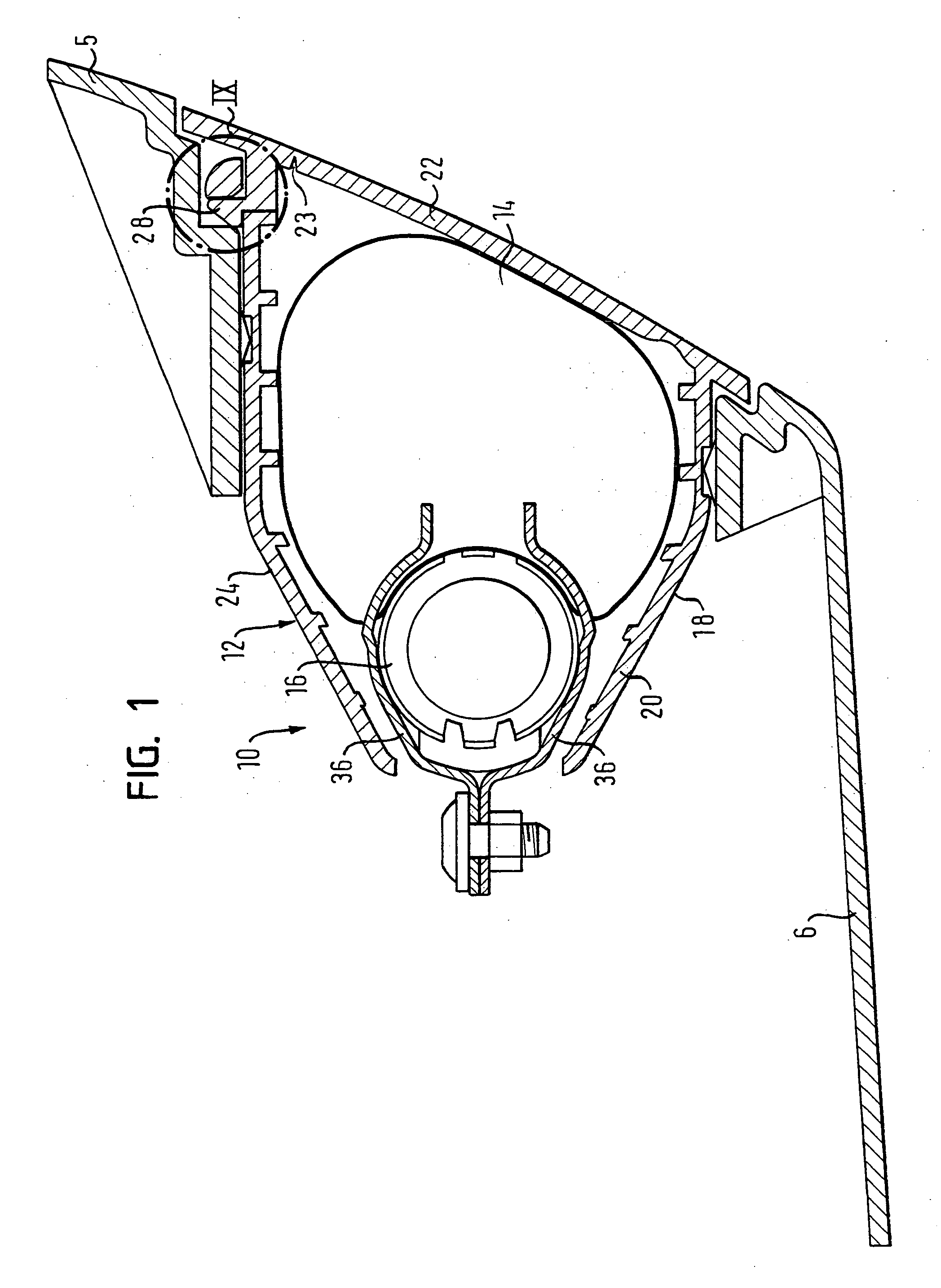
[0011]FIG. 1 shows a cross-section through a gas bag module in accordance with the invention, the gas bag module being placed in an instrument carrier;

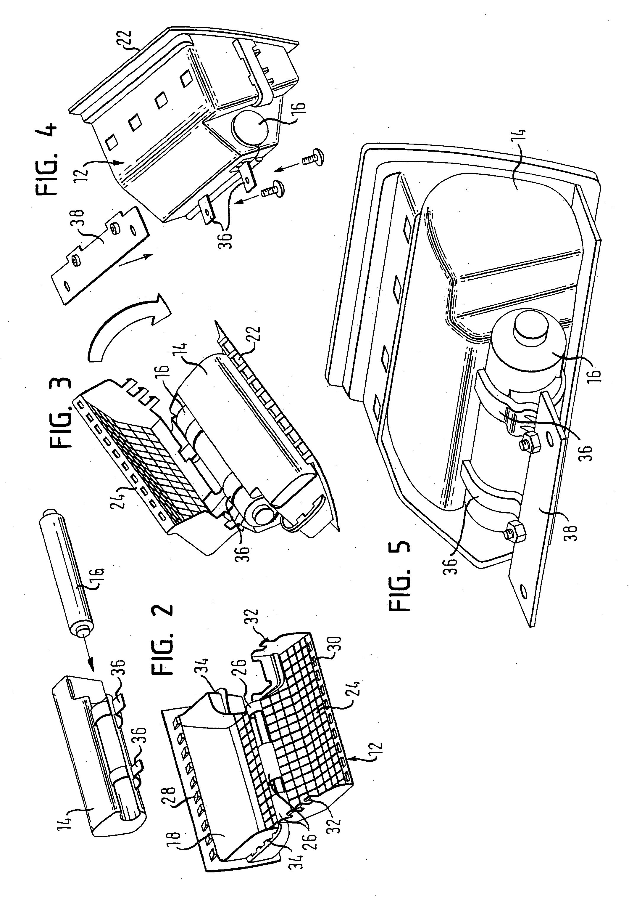
[0012] FIGS. 2 to 4 show various assembly steps of the gas bag module;

[0013]FIG. 5 shows the unit formed of the gas generator and the gas bag arranged in the interior of the housing;

[0014]FIG. 6 shows the fitting of the assembled gas bag module in an instrument carrier;

[0015]FIGS. 7 and 8 show various views of the assembled gas bag module; and

[0016] FIGS. 9 to 11 show the latching lugs used for closing off the housing prior to closing, during closing and after closing.

[0017] In FIG. 1 there is shown an instrument carrier 5 holding, for example at the driver side, instruments such as a speedometer or a revolution counter or, at the front passenger side, a glove compartment. In the lower region of the instrument carrier 5, i.e. in the transition portion to a section 6 facing the foot space, there is provided a gas bag module 10 com...


PUM


Abstract

A gas bag module (10), in particular for a knee gas bag, includes a housing (12), a gas generator (16) and a gas bag (14). The gas generator (16) and the gas bag (14) form a unit which is floatingly mounted in the interior of the housing (12).

Description

BACKGROUND OF THE INVENTION [0001] The invention relates to a gas bag module, in particular for a knee air bag, including a housing, a gas generator and a gas bag. [0002] Knee air bags are provided in particular in motor vehicles destined for the U.S. market or countries in which the wearing of safety belts is not statutory. In a frontal collision the knee air bag permits to restrain the knees of the vehicle occupant. This prevents the vehicle occupant from slipping into the region below the instrument carrier. The upper trunk of the vehicle occupant is caught by a conventional gas bag. [0003] Usually, the individual components of a knee gas bag module are fitted to a fastening plate made of metal. Should the gas bag be activated, this fastening plate takes up all response forces and supports the gas bag against the vehicle occupant. The fastening plate further serves as a housing and thus as a protective cover against damage and soiling of the individual components. Moreover, it ma...

Claims


Application Information

Patent Timeline
IPC IPC(8): B60R21/16B60R21/205
CPCB60R21/206
Inventor FREISLER, WERNERZISCHKA, GERD
Owner TRW AUTOMOTIVE GMBH
Why Eureka
Try Eureka