Backlight assembly

Active Publication Date: 2005-09-08
AU OPTRONICS CORP
View PDF9 Cites 36 Cited by
  • Summary
  • Abstract
  • Description
  • Claims
  • Application Information

AI Technical Summary

Benefits of technology

[0009] It is therefore an object of the invention to provide a backlight assembly, which fixes at least the optical film in at least two directions by using a number of contact edges of each of the positioning flanges of the optical film to abut against at least one edge of the frame in at least two of directions, not only improves th

Problems solved by technology

Consequently, additional parts costs and manufacturing processes will be needed.
Moreover, since the conventional method according to FIG. 1A cannot fix the whole optical film precisely, the optical film is easily wrinkled, leading to a significant deterioration of luminance quality.
However, the scraps of optical film obtained from hollowing cannot be recycled adding t

Method used


Image

  • Backlight assembly
  • Backlight assembly
  • Backlight assembly

Examples


Example

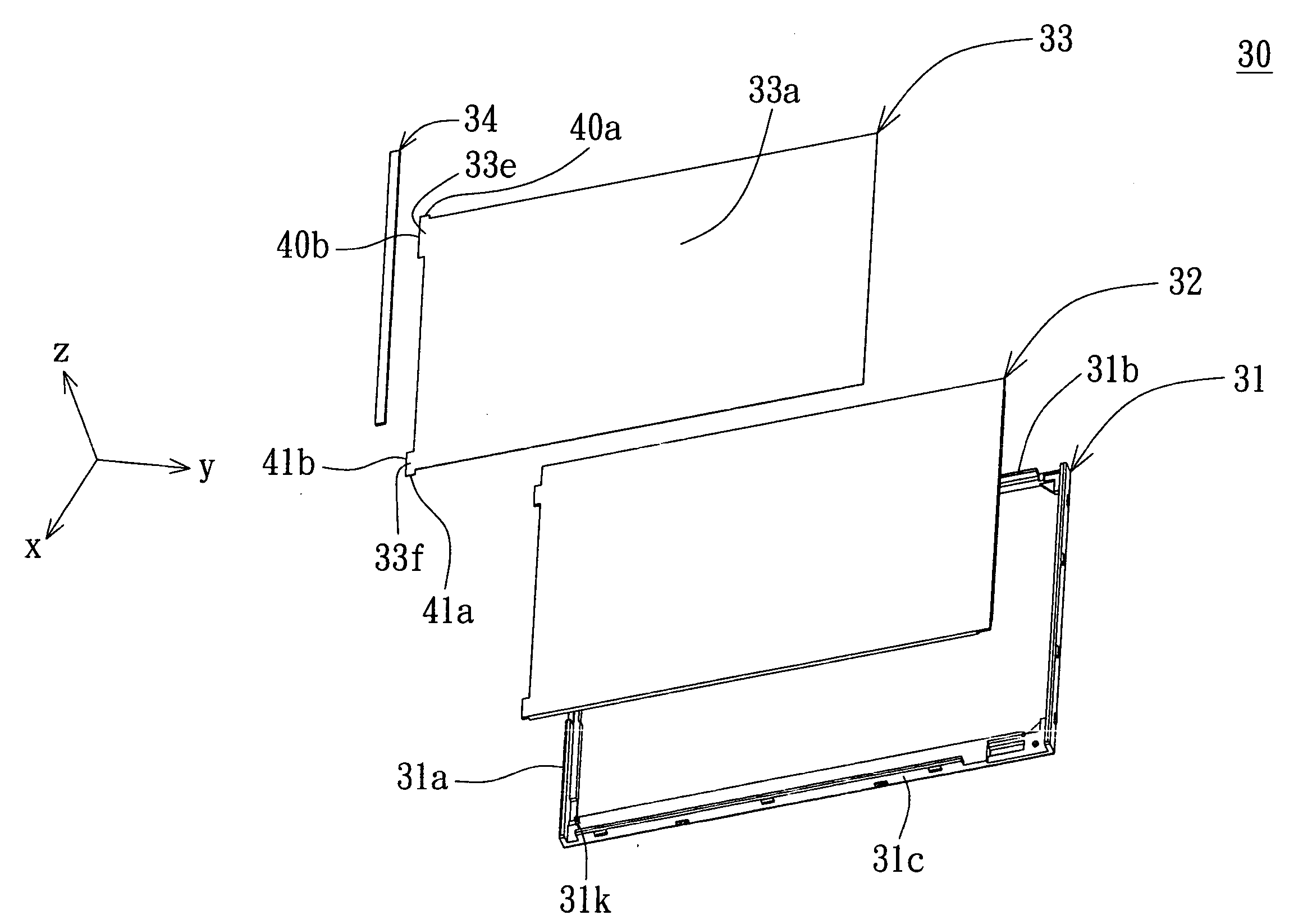
[0021] Please refer to FIGS. 2˜4 at the same time. FIG. 2 shows an explosive diagram of a backlight assembly according to the preferred embodiment of the invention; FIG. 3 shows a partial explosive diagram of the optical film and frame in FIG. 2; and FIG. 4 shows an assembly diagram of the optical film and frame in FIG. 3. In FIG. 2, a backlight assembly 30 includes a frame 31, a light guide plate 32, a light-shielding layer 34, and at least one optical film. An optical film 33 is exemplified in the disclosure of the invention. The frame 31 at least includes frame edges 31a, 31b and 31c, wherein the frame edge 31a connects the two opposing frame edges 31b and 31c. The light of the backlight assembly 30 has a light source, which is disposed on the frame 31 and is located under a surface of the light guide plate 32 or besides a side of the light guide plate 32.

[0022] The optical film 33 includes a light incident surface 33a and at least one positioning flanges, wherein the positionin...


PUM


Abstract

A backlight assembly is provided. The backlight assembly including a frame, a light source, and at least one optical film. The light source is disposed on the frame. The optical film has at least one positioning flange. The positioning flange includes at least two contact edges configured to abut against at least one edge of the frame in at least two directions to hold the optical film in place relative to the frame.

Description

[0001] This application claims the benefit of Taiwan application Serial No. 093105611, filed Mar. 3, 2004, the subject matter of which is incorporated herein by reference. BACKGROUND OF THE INVENTION [0002] 1. Field of the Invention [0003] The invention relates in general to a backlight assembly, and more particularly to a backlight assembly whose optical films are hold in the frame while the positioning flanges of the optical films are configured to abut against the edges of the frame in a number of directions. [0004] 2. Description of the Related Art [0005] Featured by the advantages of lightweight, slimness, power saving and low radiation Liquid crystal display (LCD) has gained rapid advance in manufacturing technology and has been widely applied in electronic devices such as personal digital assistant (PDA), notebook, digital still camera, digital video recorder, mobile phone, computer monitor and TV screen. Further due to gorgeous amount in R&D investment and the adoption of la...

Claims


Application Information

Patent Timeline
IPC IPC(8): A47F3/00F21V7/04G02F1/1335G02F1/13357H03H9/00
CPCG02F2201/465G02F1/133608
Inventor CHANG, CHE-CHIHLO, CHI-CHUNG
Owner AU OPTRONICS CORP
Why Eureka
Try Eureka