Injection molding apparatus

Active Publication Date: 2010-12-09
HONDA MOTOR CO LTD
View PDF4 Cites 0 Cited by
  • Summary
  • Abstract
  • Description
  • Claims
  • Application Information

AI Technical Summary

Benefits of technology

[0018]The present invention has an object of providing an injection molding apparatus that can reduce material waste.
[0021]According to this invention, in addition to between the communication passage and the nozzle body, a heater is inserted between the communication passage and the flange portion as well. Accordingly, resin of a great amount can be prevented from adhering to a vicinity of this flange portion since the flange portion of the hot nozzle can be reliably heated by way of driving the heater. Therefore, since it is possible to make the resin layer adhering to the channel thin and uniform, the number of times conducting throw-away molding is made few, and thus material waste can be reduced.
[0024]However, according to this invention, since the flange portion is made to abut the manifold, the boundary surface of the channel is only a connecting portion of the flange portion and the manifold. Therefore, compared to a case in which there is a plurality of boundary surfaces, material waste can be further reduced since heat radiation can be prevented.
[0025]According to the present invention, in addition to between the communication passage and the nozzle body, a heater is inserted between the communication passage and the flange portion as well. Accordingly, resin of a great amount can be prevented from adhering to a vicinity of this flange portion since the flange portion of the hot nozzle can be reliably heated by way of driving the heater. Therefore, since it is possible to make the resin layer adhering to the channel thin and uniform, the number of times conducting throw-away molding is made few, and thus material waste can be reduced.

Problems solved by technology

The resin of the previous color cures and adheres to the insides of the hot runner and the hot nozzle, and the resin thus adhered cannot be completely discharged by throw-away molding one time.
Since this molded article from throw-away molding cannot be used as a finished product, there has been a problem in there being a lot of wasted material.

Method used


Image

  • Injection molding apparatus
  • Injection molding apparatus

Examples


Embodiment Construction

[0027]An embodiment of the present invention will be explained below based on the drawing.

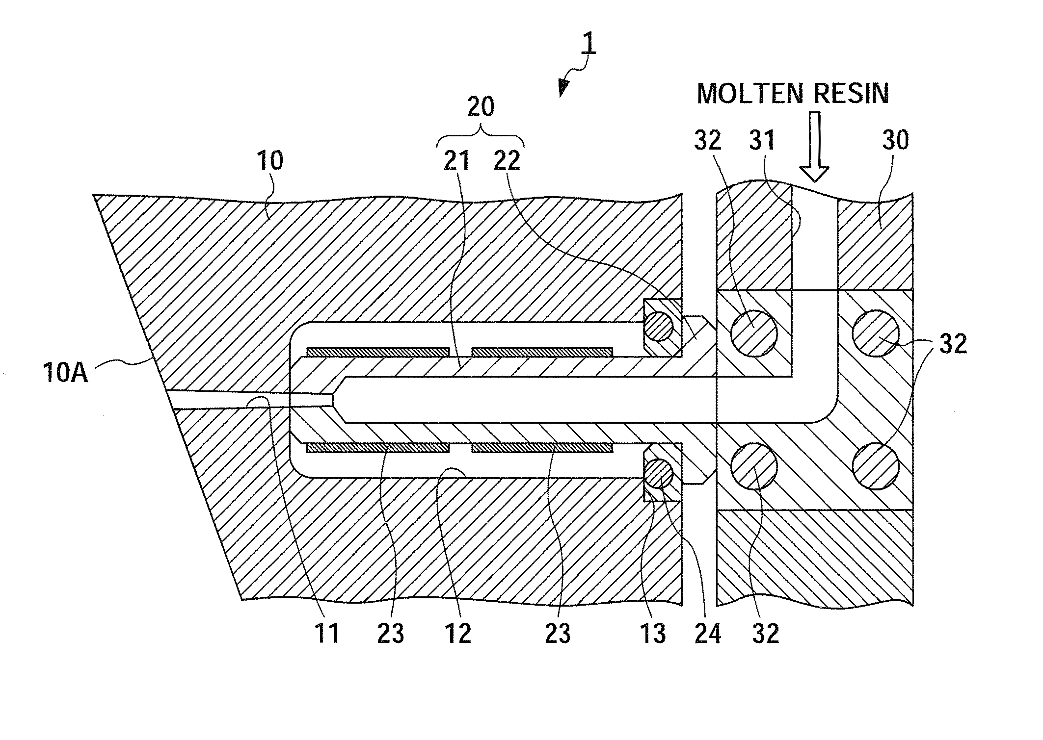
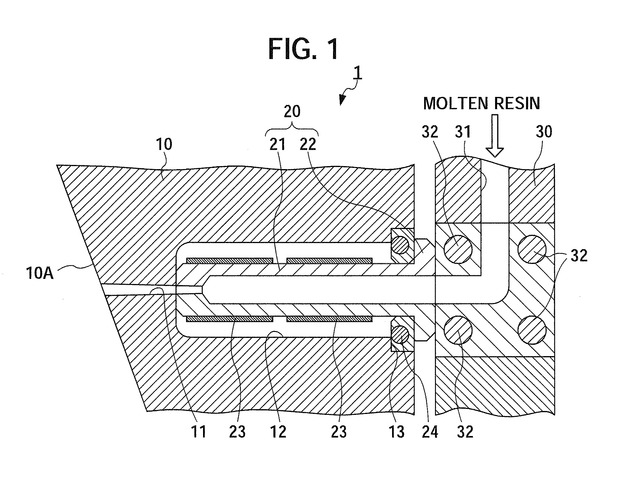
[0028]FIG. 1 is a schematic diagram of an injection molding apparatus according to an embodiment of the present invention.

[0029]The injection molding apparatus 1 is an apparatus that performs injection molding of thermoplastic resin. The injection molding apparatus 1 is provided with a die 10 having a hot nozzle 20 that is in communication with a cavity 10A, a manifold 30 that is formed by a hot runner 31 connected to the hot nozzle 20 of this die 10, and a plurality of cylinder devices not illustrated that supply molten resin to this hot runner 31.

[0030]Heaters 32 that heat the hot runner 31 are built into the manifold 30.

[0031]A communication passage 11 that is in communication with the cavity 10A is formed in the die 10. A portion on a side of the manifold 30 of this communication passage 11 is a nozzle mounting portion 12 that has a large inside diameter. In addition, a concave portion 13 i...


PUM

PropertyMeasurementUnit
Currentaaaaaaaaaa

Abstract

An injection molding apparatus is provided that can reduce material waste. An injection molding apparatus 1 is provided with a die 10 having a hot nozzle 20, and a manifold 30 formed by a hot runner 31. A communication passage 11 that is in communication with the cavity 10A is provided in the die 10, and the hot nozzle 20 includes a nozzle body 21 of a cylindrical shape that is inserted in the communication passage 11, and a flange portion 22 that is formed at an end side of this nozzle body 21 and is exposed outside of the communication passage 11, in which a band heater 23 that heats this nozzle body 21 is inserted between the communication passage 11 and the nozzle body 21, and a ring heater 24 that heats this flange 22 is inserted between the communication passage 11 and the flange 22.

Description

[0001]This application is based on and claims the benefit of priority from Japanese Patent Application No. 2009-133691, filed on 3 Jun. 2009, the content of which is incorporated herein by reference.BACKGROUND OF THE INVENTION[0002]1. Field of the Invention[0003]The present invention relates to an injection molding apparatus. More specifically, it relates to an injection molding apparatus provided with a die having a hot nozzle that is in communication with a cavity, and a manifold formed by hot runner connected to this hot nozzle.[0004]2. Related Art[0005]Heretofore, an injection molding apparatus has been known that performs injection molding of thermoplastic resins. This injection molding apparatus is provided with a die having a hot nozzle that is in communication with a cavity, a manifold formed by hot runner connected to this hot nozzle, and a cylinder device that supplies molten resin to this hot runner.[0006]A heater that heats the hot runner is built into the manifold.[0007...

Claims


Application Information

Patent Timeline
IPC IPC(8): B29C45/74
CPCB29C2045/2754B29C45/2737
Inventor SATO, TAKAAKIKATO, TAKASHIKURIYAMA, TAKESHI
Owner HONDA MOTOR CO LTD
Why Eureka
Try Eureka