
Silicon slider for magnetic recording fabricated by an alkaline etch

Inactive Publication Date: 2006-08-24
WESTERN DIGITAL TECH INC
View PDF9 Cites 0 Cited by
  • Summary
  • Abstract
  • Description
  • Claims
  • Application Information

AI Technical Summary

Benefits of technology

[0013] The present invention provides an economic method for constructing a slider from a Si wafer that significantly reduces wafer material waste during the parsing of the wafer into slider rows. According to the present invention, a plurality of read / write heads are patterned in a plurality of rows onto a Si wafer. A mask is formed over the wafer, the mask having an opening or trench formed between the rows of sliders. The wafer is then exposed to an etchant such as which removes wafer material to form a trench straight down into the wafer.
[0017] By using the KOH etching method of the present invention, rows can be formed with a very small kerf loss of only 30 to 50 um after etching through a 1 mm thick silicon wafer. The present cutting process of the present invention can have a very high throughput and very low capital equipment cost compared to DRIE.

Problems solved by technology

As can be appreciated, such saw blades can only be made so thin, and as a result a significant amount of the wafer is wasted as unused kerf region to accommodate the width of the saw cut between each row.
Since the price margins for the production of magnetic sliders is very tight, manufactures must produce as many usable sliders as possible from each wafer.
Therefore, since the sawing of wafers into rows consumes a large percentage of the wafer as unusable kerf region, such sawing reduces yield and increases the cost of a slider.
It turns out that Al—TiC is not the ideal material for use in a slider.
Al—TiC is an extremely hard material and can be prone to causing media damage during head disk contact.
The sawing operation used to cut the wafer into rows creates very high stresses on the wafer material.
If this sawing operation is used on a comparatively less tough material such as Si, the stress on the wafer material during the sawing operation causes chipping and cracking in the rows.
Some of these cracks may be propagated at some later point, including during operation in the disk drive.
Also, chipping or cracking at the ABS results in an unacceptable change in flying characteristics, thereby making diamond saw cutting an undesirable process for making Si rows.
The wedge angle can cause some problems with handling the sliders and with lapping and other manufacturing steps.
The use of DRIE also requires the use of expensive tooling since each DRIE tool costs up to one million dollars and has very low wafer throughput.

Method used


Image

  • Silicon slider for magnetic recording fabricated by an alkaline etch
  • Silicon slider for magnetic recording fabricated by an alkaline etch
  • Silicon slider for magnetic recording fabricated by an alkaline etch

Examples


Embodiment Construction

[0025] The following description is of the best embodiments presently contemplated for carrying out this invention. This description is made for the purpose of illustrating the general principles of this invention and is not meant to limit the inventive concepts claimed herein.

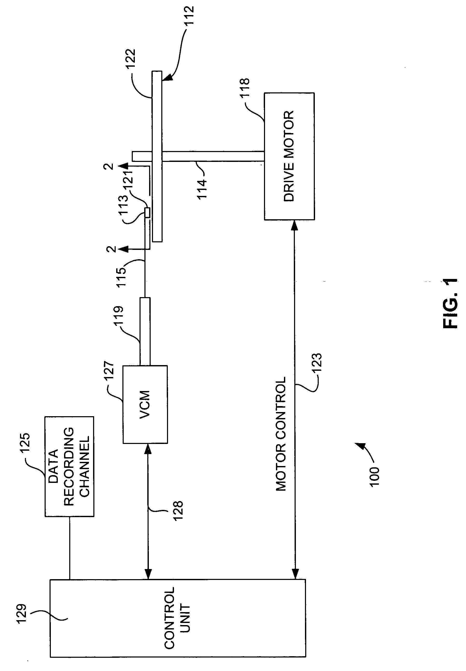
[0026] Referring now to FIG. 1, there is shown a disk drive 100 embodying this invention. As shown in FIG. 1, at least one rotatable magnetic disk 112 is supported on a spindle 114 and rotated by a disk drive motor 118. The magnetic recording on each disk is in the form of annular patterns of concentric data tracks (not shown) on the magnetic disk 112.

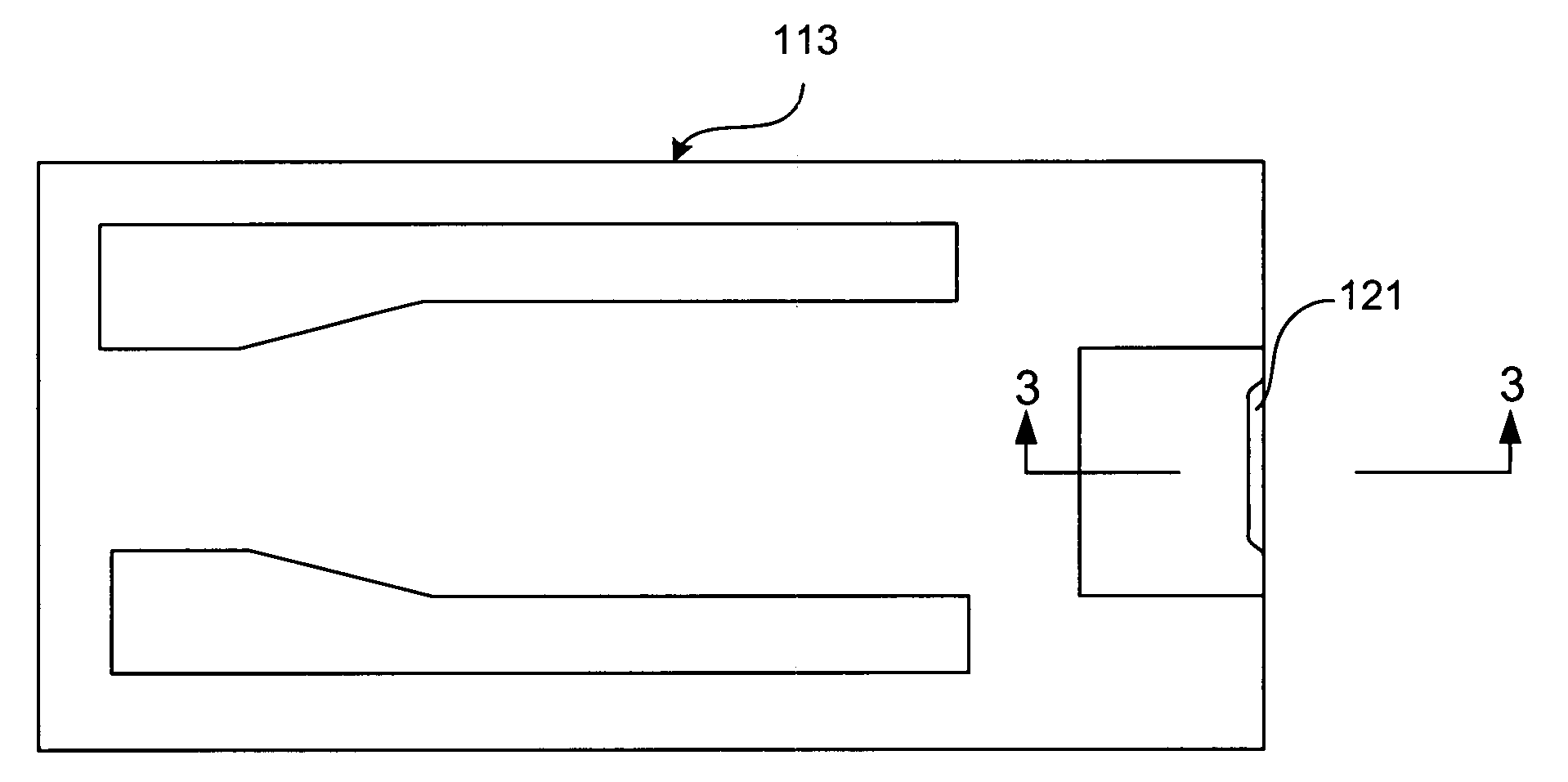
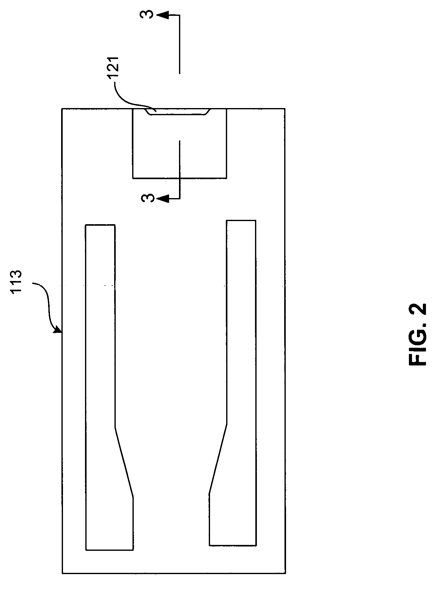
[0027] At least one slider 113 is positioned near the magnetic disk 112, each slider 113 supporting one or more magnetic head assemblies 121. As the magnetic disk rotates, slider 113 moves radially in and out over the disk surface 122 so that the magnetic head assembly 121 may access different tracks of the magnetic disk where desired data are written. Each sli...


PUM

PropertyMeasurementUnit
Widthaaaaaaaaaa
Widthaaaaaaaaaa
Structureaaaaaaaaaa

Abstract

A slider for use in a magnetic data recording system that is constructed from a Si wafer by a method that saves valuable wafer real estate by minimizing kerf related to the cutting of the wafer into slider rows. The sliders are produced from a (110) oriented Si wafer, and the sliders are parsed into rows by a process that involves forming a mask having a trench or opening between the rows of sliders at the location of the desired cut and parallel to a vertical (111) plane of the wafer. The wafer is then exposed to KOH which removes wafer material in the vertical direction through the wafer without removing wafer material in the horizontal direction. The vertical removal of wafer material is due to the extreme preferential removal of the (110) surface Si over that of the (111) surface Si. This results in a narrow straight trench being formed. The KOH etch removal can form a trench or cut having a width of only 30 to 50 um through a 1 mm thick wafer.

Description

FIELD OF THE INVENTION [0001] The present invention relates to the fabrication of a slider for use in magnetic recording and more particularly to the use of an alkaline etch process to parse a wafer into rows of sliders. BACKGROUND OF THE INVENTION [0002] The heart of a computer's long term memory is an assembly that is referred to as a magnetic disk drive. The magnetic disk drive includes a rotating magnetic disk, write and read heads that are suspended by a suspension arm adjacent to a surface of the rotating magnetic disk and an actuator that swings the suspension arm to place the read and write heads over selected circular tracks on the rotating disk. The read and write heads are directly located on a slider that has an air bearing surface (ABS). The suspension arm biases the slider toward the surface of the disk and when the disk rotates, air adjacent to the surface of the disk moves along with the disk. The slider flies on this moving air at a very low elevation (fly height) o...

Claims


Application Information

Patent Timeline
IPC IPC(8): G11B5/60
CPCG11B5/10G11B5/6005Y10T29/49048Y10T29/49041Y10T29/49046Y10T29/49052G11B5/3163G11B5/3173
Inventor REILEY, TIMOTHY CLARKSTIPE, BARRY CUSHING
Owner WESTERN DIGITAL TECH INC
Learn More