Tab mechanism

a technology of tabs and handles, applied in the field of tabs, can solve the problems of easily lost or dropped valueables, and achieve the effect of avoiding loss and damag

Inactive Publication Date: 2005-09-15
WANG WALLACE
View PDF7 Cites 12 Cited by
  • Summary
  • Abstract
  • Description
  • Claims
  • Application Information

AI Technical Summary

Benefits of technology

[0008] The primary object of the invention is therefore to specify a tab mechanism on which an identification card, a toy, a whistle, a cell phone, or objects the like are hung to avoid loss and damage.

Problems solved by technology

But, if a user forgets to close the conventional zipper 10a, the valuables are still easily lost or dropped.

Method used


Image

  • Tab mechanism
  • Tab mechanism
  • Tab mechanism

Examples


Embodiment Construction

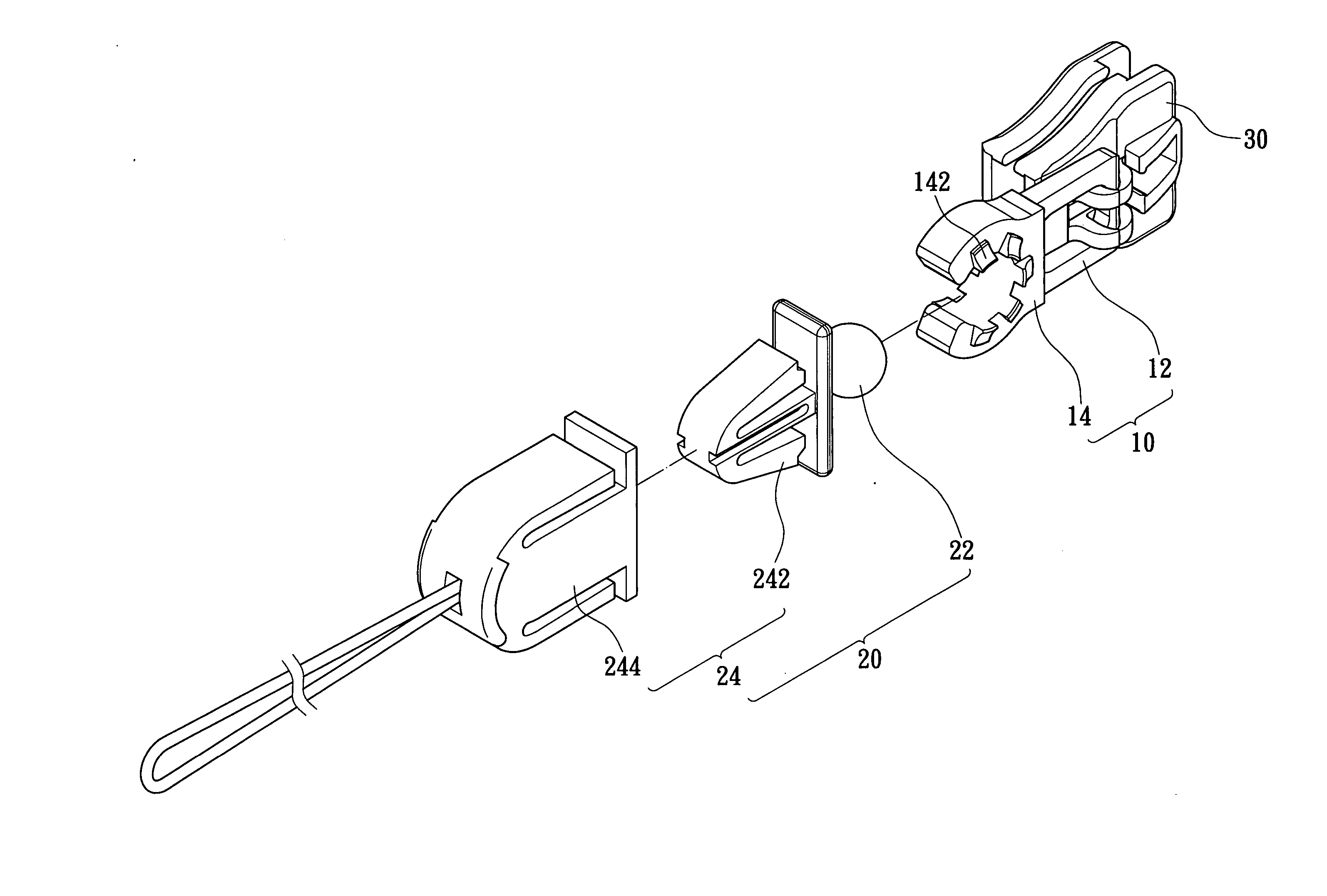
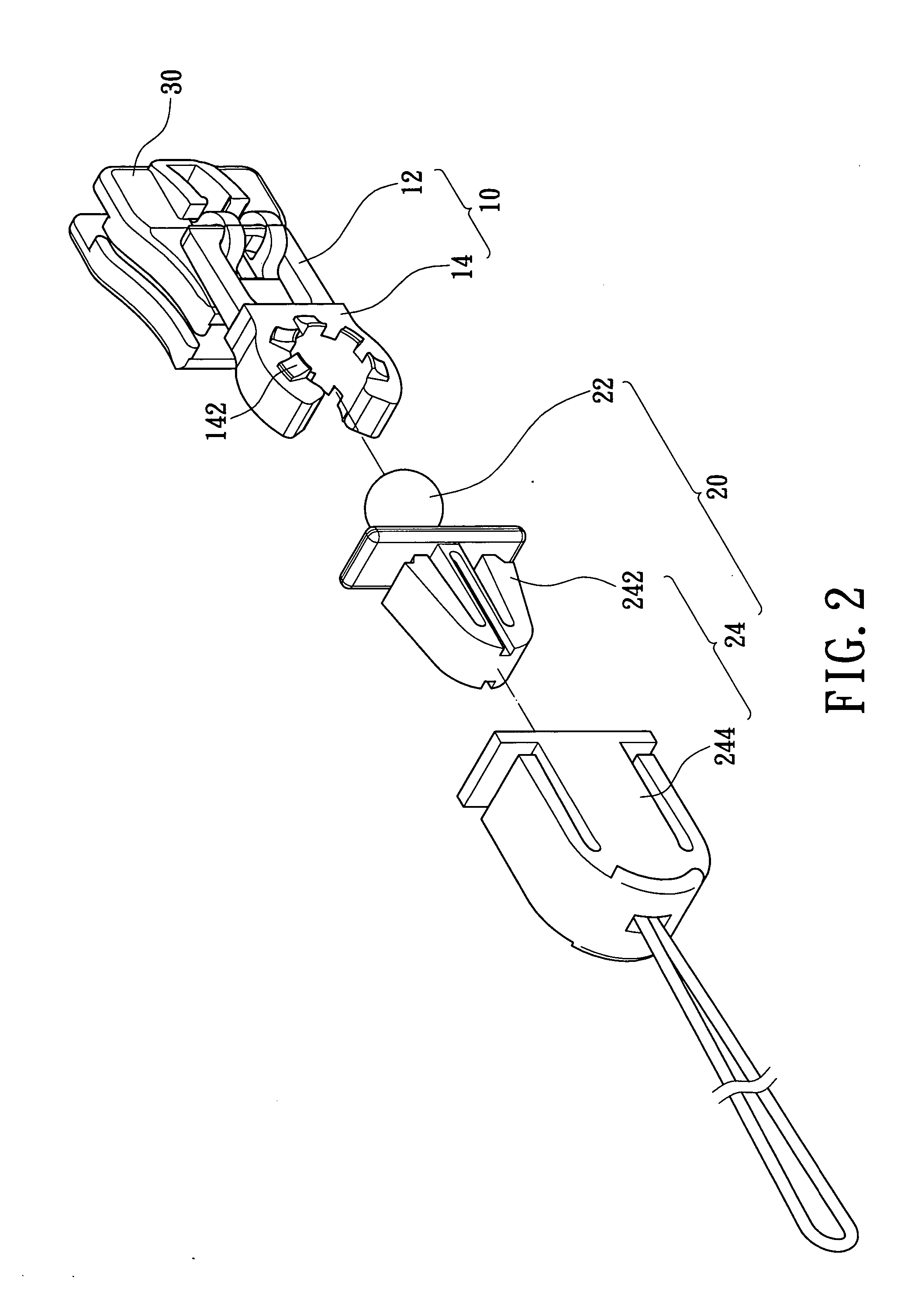
[0029] Referring to FIG. 2 to 5, the present invention provides a tab mechanism adopted for a zipper slide 30 arranged on two teeth tapes. The tab mechanism includes a connection member 10 and a locking structure; the best embodiment of the locking structure is a sphere junction 20.

[0030] The connection member 10 includes a hanging portion 12 connecting the zipper slide 30 and a clamping portion 14 downwardly extending from the hanging portion 12.

[0031] The sphere junction 20 includes a sphere body 22, a connection portion 24 under and connecting to the sphere body 22. The sphere body 22 can be clamped in the clamping portion 14 for multi-directional rotation. The best embodiment of the connection portion 24 is a detachable hook structure 24 including a bottom end for hanging an object.

[0032] The clamping portion 14 includes a plurality of curved teeth 142 respectively inwardly extending from a front inner flange and a rear inner flange of the clamping portion 14 to prevent the s...


PUM


Abstract

A tab mechanism adopted for a zipper slide has a connection member having a hanging portion connecting the zipper slide and a clamping portion downwardly extending from the hanging portion. A locking structure having a top end connects the clamping portion of the connection member and a bottom end for hanging an object. The locking structure includes a male buckle and a female buckle clamping on and detachable from the male buckle for easily hanging an identification card, a toy, a whistle, a cell phone, or similar objects to avoid loss and damage.

Description

BACKGROUND OF THE INVENTION [0001] 1. Field of the Invention [0002] The present invention relates to a tab mechanism, and particularly relates to a locking structure secured on or multi-rotating about a tab mechanism and engaging with a hanging object. [0003] 2. Background of the Invention [0004] Typical zippers are popular and generally used in everyday life due to their easy and rapid engagement and disengagement. Clothing, a bag, a wallet, and even a jacket may have a plurality of zippers arranged thereon for both utility and decoration. However, the zippers nowadays still retain original functions as well as engagement and disengagement. [0005] Referring to FIG. 1, a conventional zipper 10a adopted for a pocket includes two teeth tapes 20a, a plurality of teeth 30a respectively arranged on the two teeth tapes 20a, a slide 40a engaging with the teeth tapes 20a, and a tab 50a connecting and hanging on the slide 40a. The tab 50a is used for pulling the slide 40a to engage or diseng...

Claims


Application Information

Patent Timeline
Patent Type & Authority Applications(United States)
IPC IPC(8): A44B19/26
CPCA44B19/262Y10T24/2586Y10T24/2588A45F5/02
Inventor WANG, WALLACE
Owner WANG WALLACE
Why Eureka
Try Eureka