Micro-machined electromechanical system (MEMS) accelerometer device having arcuately shaped flexures

a micro-machined electromechanical system and accelerometer technology, applied in microstructural devices, acceleration measurement using interia forces, instruments, etc., can solve problems such as not allowing changes in material thickness

Inactive Publication Date: 2005-09-15
HONEYWELL INT INC
View PDF12 Cites 33 Cited by
  • Summary
  • Abstract
  • Description
  • Claims
  • Application Information

AI Technical Summary

Benefits of technology

[0009] The arcuate suspension apparatus of the invention is stiffer when loaded in the plane of the arcuate shape than out-of-plane. The arcuate suspension apparatus transfers in-plane loads along the included arch, which causes the arcuate suspension apparatus to be strong and rigid in opposing in-plane loads, and flexes or bends when subjected to out-of-plane loads, which causes the arcuate suspension apparatus to be flexibly compliant when loaded out-of-plane.

Problems solved by technology

However, the flexures of some prior art devices, such as those fabricated using RIE or DRIE, are essentially two-dimensional designs that do not permit changes in material thickness that can be used to control flexure stiffness.

Method used


Image

  • Micro-machined electromechanical system (MEMS) accelerometer device having arcuately shaped flexures
  • Micro-machined electromechanical system (MEMS) accelerometer device having arcuately shaped flexures
  • Micro-machined electromechanical system (MEMS) accelerometer device having arcuately shaped flexures

Examples


Embodiment Construction

[0023] In the Figures, like numerals indicate like elements.

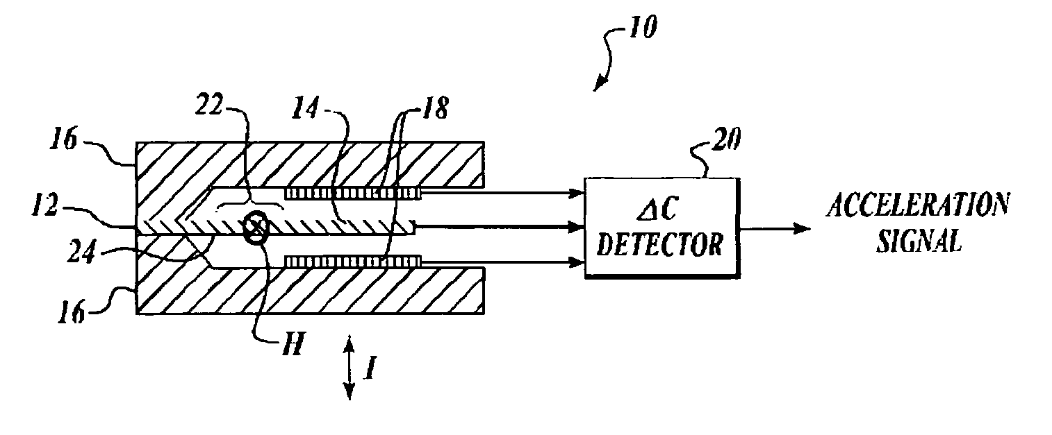
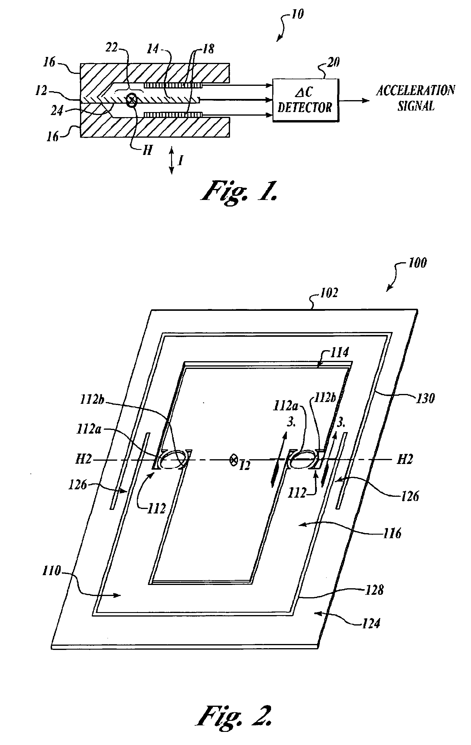
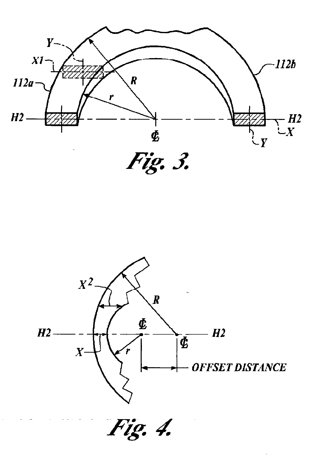
[0024] The present invention is an apparatus and method for suspending a relatively movable structure of an acceleration sensor, i.e., a proof mass, from a support structure, i.e., an inner sensor frame. The suspension apparatus of the invention includes at least first and second arcuately shaped flexures each having similar cross-sections that are relatively substantially extended in a plane in which the arcuate shape lies. The first and second arcuately shaped flexures each have a first end structured for connection to the support structure and a second end structured for connection to the movable structure that is to be suspended from the support structure. The first and second flexures both lie in the same plane and are aligned with their respective outer arcuate shapes facing oppositely each from the other and forming a hinge having an axis of rotation in the plane of the first and second arcuate shapes that extends l...


PUM


Abstract

A method for suspending a movable structure form a support structure wherein first and second flat and thin arcuately shaped flexures are formed having spaced apart substantially planar and parallel opposing surfaces, each of the first and second flexures being structured for connection between a support structure and a movable structure to be suspended from the support structure and being aligned along a common axis of rotation between the support structure and the movable structure.

Description

[0001] This application claims the benefit of allowed U.S. patent application Ser. No. 10 / 223,947 filed in the name of Mark H. Eskridge on Aug. 20, 2002, which claims the benefit of U.S. Provisional Application Ser. No. 60 / 313,777, filed in the name of Mark H. Eskridge on Aug. 20, 2001, the complete disclosures of which are incorporated herein by reference.FIELD OF THE INVENTION [0002] The present invention relates generally to micro-machined electromechanical sensor (MEMS) devices and methods for manufacturing the same, and in particular to suspension devices and methods for mounting rotational masses in MEMS devices. BACKGROUND OF THE INVENTION [0003] Many micro-machined electromechanical sensor (MEMS) devices and methods for manufacturing the same are generally well-known. See, for example, U.S. Pat. No. 6,642,067, METHOD OF TRIMMING MICRO-MACHINED ELEVTROMECHANICAL SENSORS (MEMS) dEVICES, issued Nov. 4, 2003, to Paul W. Dwyer, which is assigned to the assignee of the present app...

Claims


Application Information

Patent Timeline
Patent Type & Authority Applications(United States)
IPC IPC(8): B81B3/00G01P15/08G01P15/097G01P15/10G01P15/125
CPCB81B3/0051B81B2201/0235B81B2203/0181G01P15/125B81C2201/0133G01P15/08G01P15/097B81B2203/058G01P2015/0828G01P2015/0831
Inventor ESKRIDGE, MARK H.
Owner HONEYWELL INT INC
Why Eureka
Try Eureka