Wristwatch

Inactive Publication Date: 2005-09-22
SEIKO INSTR INC
View PDF3 Cites 38 Cited by
  • Summary
  • Abstract
  • Description
  • Claims
  • Application Information

AI Technical Summary

Benefits of technology

[0016] In this invention, it is possible to attach the band to the timepiece armor assembly by inserting the engagement member connected to the engagement/disengagement operation body into the engagement groove of the band connection part by operating the operation part of the engagement/disengagement operation body attached to the fit part after fitting the fit part provided in an end part of the band to the connection groove of the band connection part along the thickness direction. Further, by a procedure reverse to this, it is possible to detach the band from the timepiece armor assembly. In such an attachment/detachment of the band, since the connection groove and the fit part are large in their shapes, a mutual fit and its release are easy. Moreover, the attachment or the detachment of the fit part to or from the band connection part can be performed along their thickness directions. Besides, since the operation part of the engagement/disengagement operation body is disposed in the exposed face of the fit part exposed in the back face or the front face of the band connection part, when operating the operation part, there is no fact that the band connection part of the timepiece armor assembly becomes the obstacle

Problems solved by technology

In the Patent Document 1, when attaching or detaching the band to or from the timepiece armor assembly, a work must be performed in a space between one pair of bow feet of the timepiece armor assembly, in other words, within a bow crotch a limited slight interstice between an axle end of a large diameter axle part of the spring bar and the bow foot opposed to the axle end at a very short distance, so that the bow foot becomes an obstacle and thus an operation property for attaching or detaching the band is bad.
Moreover, in this attachment/detachment operation, there is required a tool for exclusive

Method used


Image

  • Wristwatch
  • Wristwatch
  • Wristwatch

Examples


Embodiment Construction

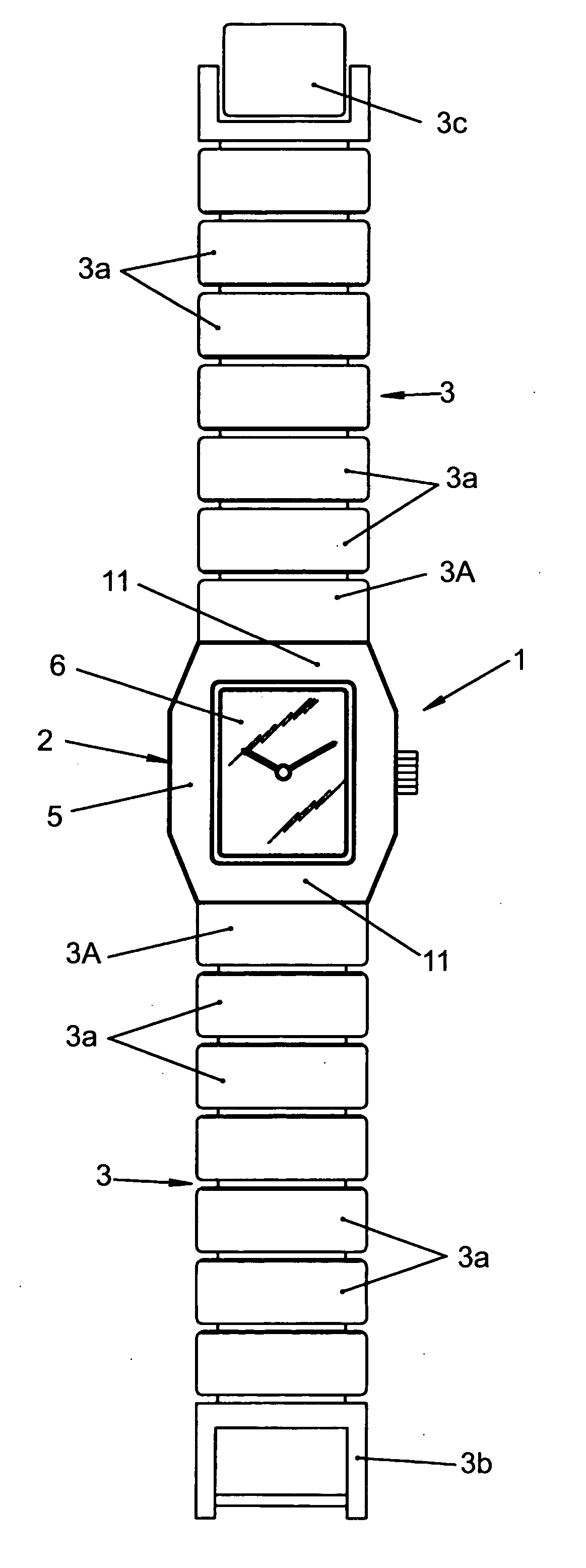
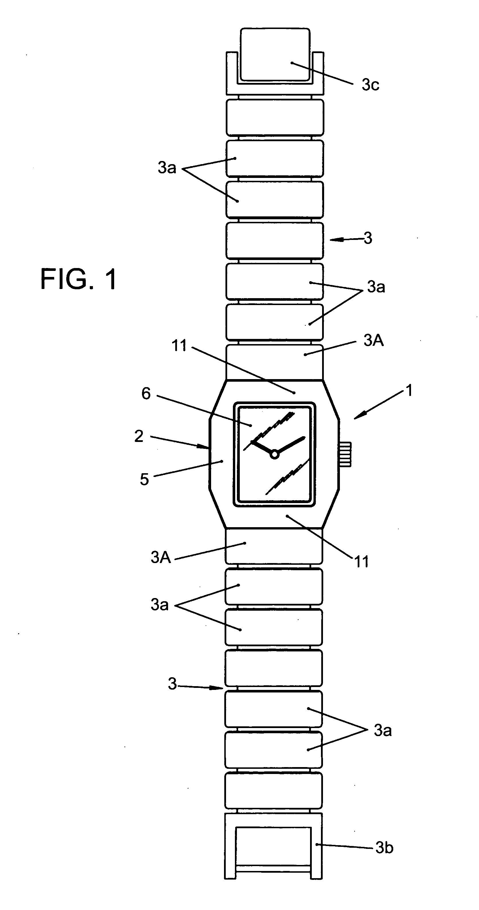
[0028] A 1st embodiment of the present invention is explained by referring to FIG. 1-FIG. 6.

[0029] In a wristwatch 1 shown in FIG. 1, a band 3 is attached to a timepiece armor assembly 2. The timepiece armor assembly 2 possesses a constitution in which a transparent member, e.g., a glass 6, causing a dial to be seen is mounted to a front face of a case band 5 made of a metal for instance, and a case back not shown in the drawing has been detachably screwed in to a back face of the case band 5. In this timepiece assembly 2, there are accommodated the dial, a timepiece movement not shown in the drawing, and the like.

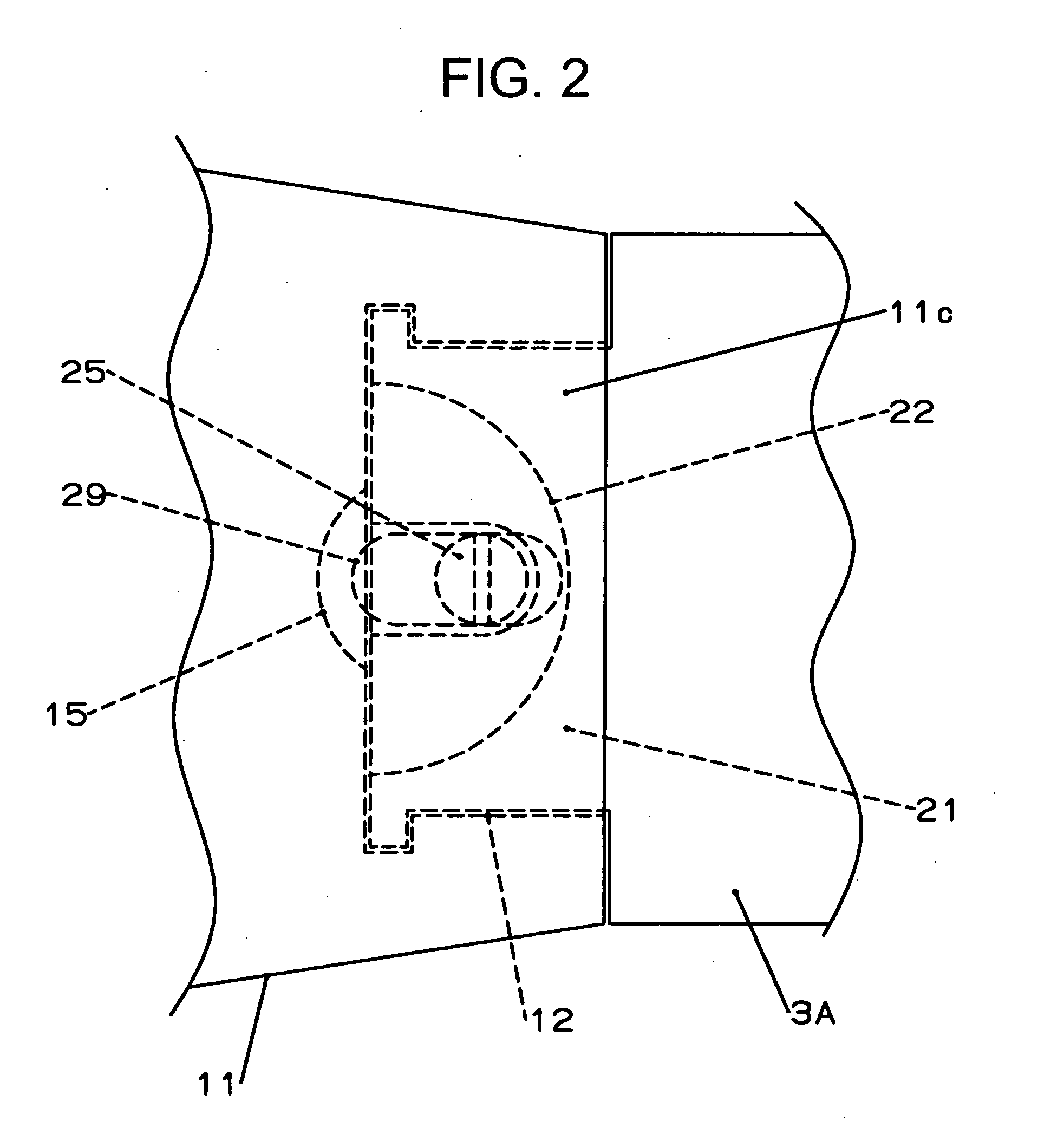
[0030] The case band 5 of the timepiece armor assembly 2 monolithically has band connection parts 11 corresponding to 6 o'clock and 12 o'clock sides of the dial and, as mentioned later, the band 3 is detachably attached to each of these band connection parts 11. The band 3 is made of the same material as the case band 5, e.g., the same metal as the case band 5, and plura...


PUM


Abstract

To provide a wristwatch in which a band can be easily attached to or detached from a timepiece armor assembly. In a band connection part of a timepiece armor assembly, there are provided respectively a connection groove which opens respectively to a back face 11a and an end face of this connection part and whose interior is formed wider than an open end of the end face, and an engagement groove opening to the former groove. A fit part having a shape coinciding with the connection groove and detachably fitted to the connection groove is provided in an end part of a band attached to or detached from the band connection part. An engagement member, which is protruded into or retracted form an opposed face facing on the engagement groove under a state that the fit part has been fitted to the connection groove and thereby inserted into or detached from the engagement groove, is attached to the fit part. An engagement/disengagement operation body, which has an operation part disposed in an exposed face of the fit part exposed in the back face of the band connection part under the state that the fit part has been fitted to the connection groove, is attached to the fit part. The engagement member is attached to the engagement/disengagement operation body.

Description

BACKGROUND OF THE INVENTION [0001] 1. Field of the Invention [0002] The present invention relates to a wristwatch in which a band has been detachably connected to a timepiece armor assembly. [0003] 2. Description of the Prior Art [0004] Hitherto, the band is detachably attached to the timepiece armor assembly by using a spring bar inserted through an axle insertion part provided in an end part of the band (for example, refer to Patent Document 1). [0005] Specifically, the spring bar has in its both ends movable pins, and is formed by building therein a coil spring biasing these movable pins in a direction separating each other. The band is attached to the timepiece armor assembly by inserting one movable pin of this spring bar into one of stop holes respectively provided in one pair of bow feet of the timepiece armor assembly, and thereafter inserting the other movable pin into the other of the stop holes. Reversely to this, it is possible to detach the band from the timepiece armor...

Claims


Application Information

Patent Timeline
IPC IPC(8): G04B37/16A44C5/14B65D39/00B65D41/00B65D43/00B65D47/00B65D51/00G04B37/00G04B37/14G04B37/18
CPCG04B37/1486
Inventor HIRANUMA, HARUKIOMORI, NOBUKAZU
Owner SEIKO INSTR INC
Why Eureka
Try Eureka