Die casting apparatus

a technology of die casting and apparatus, applied in the field of die casting apparatus, can solve problems such as affecting maintenance efficiency, and achieve the effect of wide work spa

Active Publication Date: 2016-06-14
TOYOTA JIDOSHA KK
View PDF4 Cites 0 Cited by
  • Summary
  • Abstract
  • Description
  • Claims
  • Application Information

AI Technical Summary

Benefits of technology

[0014]According to the one aspect of the invention, it is possible to prevent the pump from becoming an obstacle to a maintenance work performed by a worker, thereby ensuring a sufficiently wide work space around the die casting apparatus.

Problems solved by technology

This configuration makes a work space for replacing, for example, a plunger tip or a support shaft narrow, thus hindering the maintenance efficiency.

Method used


Image

  • Die casting apparatus
  • Die casting apparatus
  • Die casting apparatus

Examples


Embodiment Construction

[0024]Hereinafter, an example embodiment of the invention will be described. It should be noted that the technical scope of the invention is not be limited to the following embodiment.

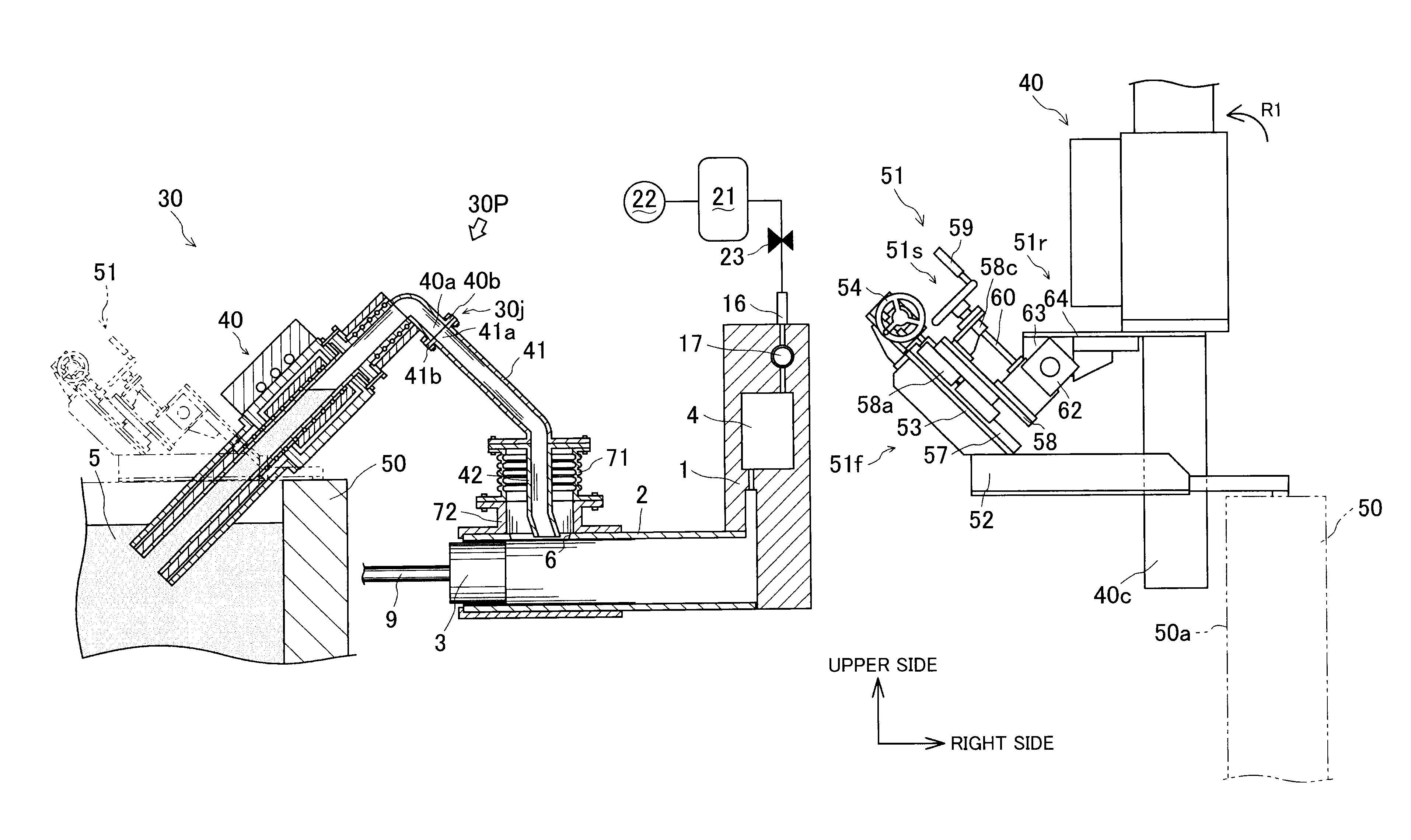
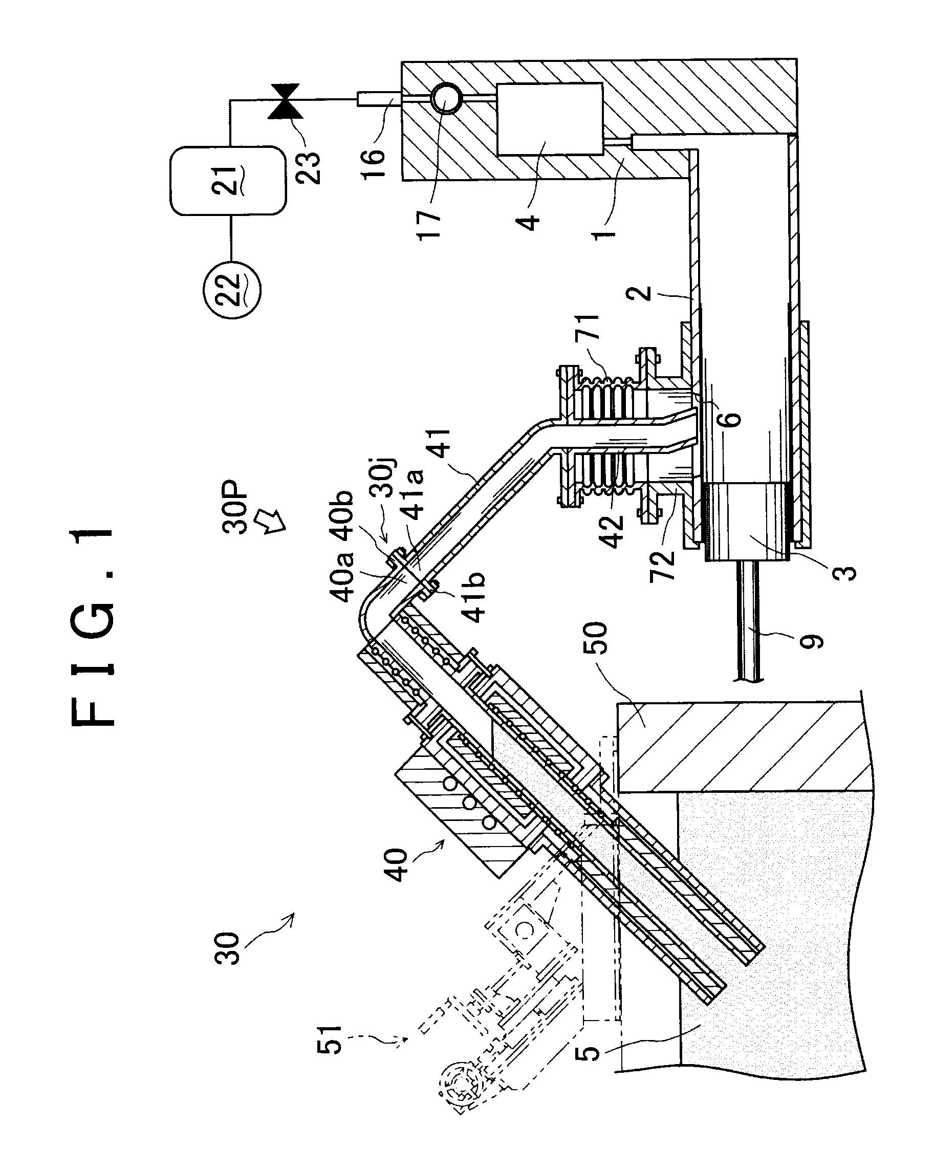
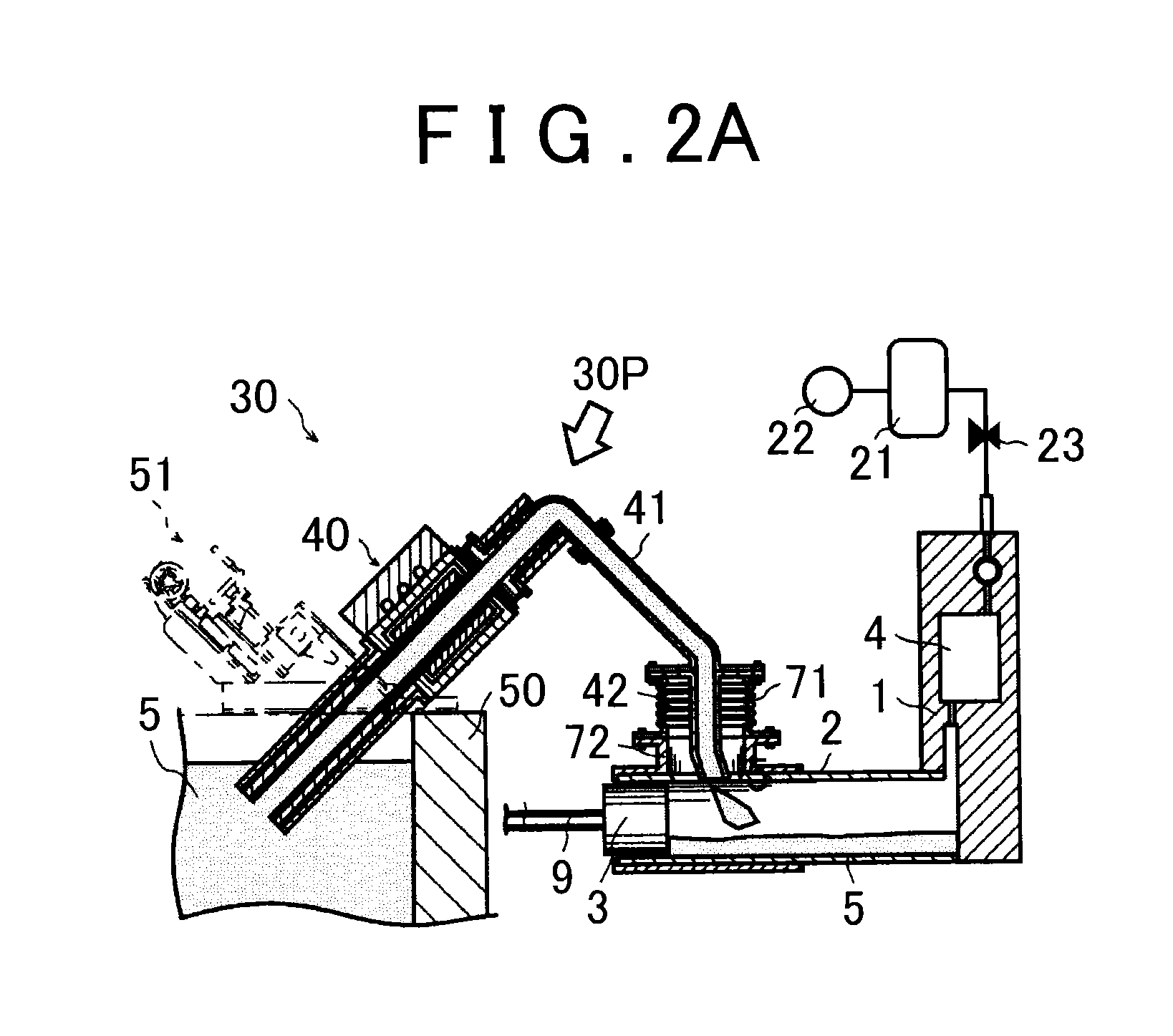
[0025]A die casting apparatus 30 according to an embodiment of the invention will be described with reference to FIG. 1. In this specification, description will be provided with the right side in FIG. 1 being the right side of the die casting apparatus 30 and the left side in FIG. 1 being the left side of the die casting apparatus 30, for the sake of convenience.

[0026]As illustrated in FIG. 1, a mold 1 of the die casting apparatus 30 has a cavity 4, and the mold 1 is provided with a plunger sleeve 2 in a generally cylindrical shape. The plunger sleeve 2 is communicated with the cavity 4 and protrudes leftward from the mold 1. A plunger tip 3 in a short columnar shape is configured to be slid rightward in the plunger sleeve 2 to extrude molten metal 5 such as aluminum fed into the plunger sleeve 2, ther...


PUM

PropertyMeasurementUnit
angleaaaaaaaaaa
voltageaaaaaaaaaa
shapeaaaaaaaaaa

Abstract

A die casting apparatus includes: an electromagnetic pump body disposed at a plunger sleeve-side end portion of a molten metal holding furnace; and a connecting pipe connected to the electromagnetic pump body and the plunger sleeve to provide communication between the electromagnetic pump body and a molten metal feed port, the connecting pipe being separable from the electromagnetic pump body. The die casting apparatus further includes a moving mechanism configured to allow the electromagnetic pump body to move between an inclined state where the electromagnetic pump body is inclined with respect to a horizontal plane in the molten metal holding furnace at an angle of approximately 45 degrees and an upright state where the electromagnetic pump body is perpendicular to the horizontal plane in the molten metal holding furnace.

Description

INCORPORATION BY REFERENCE[0001]The disclosure of Japanese Patent Application No. 2014-157099 filed on Jul. 31, 2014 including the specification, drawings and abstract is incorporated herein by reference in its entirety.BACKGROUND OF THE INVENTION[0002]1. Field of the Invention[0003]The invention relates generally to a die casting apparatus, and more specifically to a die casting technique of performing casting by injecting molten metal into a cavity of a mold.[0004]2. Description of Related Art[0005]In a die casting apparatus according to related art, the following technique is adopted: a pump disposed at a molten metal holding furnace and a molten metal feed port of a plunger sleeve are communicated with each other through a connecting pipe; and molten metal drawn by the pump up from the molten metal holding furnace is injected into the plunger sleeve through the connecting pipe (see, for example, Japanese Patent Application Publication No. 2013-66896 (JP 2013-66896 A)).[0006]In t...

Claims


Application Information

Patent Timeline
Patent Type & Authority Patents(United States)
IPC IPC(8): B22D17/30B22D17/04B22D17/20
CPCB22D17/04B22D17/20B22D17/30B22D17/10B22D17/2015
Inventor TOMITA, TAKASHIKIKUCHI, MAKOTOKOGANEZAWA, TAKAYUKIKAYASHITA, YUJI
Owner TOYOTA JIDOSHA KK
Why Eureka
Try Eureka